Advertisement
A419 Series Electronic Temperature Controls
with NEMA 1 or NEMA 4X Watertight Enclosures
Application
IMPORTANT:
The A419 Series Electronic
Temperature Controls are intended to control
equipment under normal operating conditions.
Where failure or malfunction of an A419 control
could lead to an abnormal operating condition that
could cause personal injury or damage to the
equipment or other property, other devices (limit or
safety controls) or systems (alarm or supervisory)
intended to warn of or protect against failure or
malfunction of the A419 control must be
incorporated into and maintained as part of the
control system.
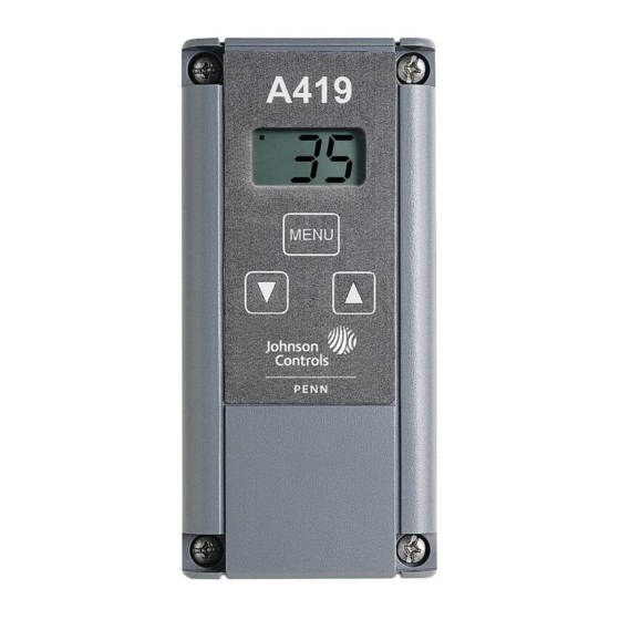
The A419 Electronic Temperature Control is a
single-stage, electronic temperature control with a
Single-Pole, Double-Throw (SPDT) output relay. The
control features a lockable, three-button touchpad for
setup and adjustment and a Liquid Crystal Display
(LCD) which displays the sensed temperature and
other control functions. A front panel Light-Emitting
Diode (LED) indicates the output relay status. The
control has a setpoint range of -30 to 212°F
(-34 to 100°C) and is available in 24 VAC or
120/240 VAC models. See the Technical
Specifications section.
The A419 control has heating and cooling modes with
adjustable setpoint and differential, an adjustable
anti-short cycle delay, and a temperature offset
(setback) function. The control provides remote
sensing capability, and electronic accuracy in a
Type NEMA 1 high-impact plastic enclosure suitable
for surface or DIN rail mounting or a surface mount
Type NEMA 4X watertight and corrosion resistant
enclosure. The temperature sensor supplied with the
control is interchangable with compatible
Johnson Controls/PENN® A99 temperature sensors.
Canadian Compliance Statement
This digital apparatus does not exceed the Class A
limits for radio noise emissions from digital apparatus
set out in the Radio Interference Regulations of the
Canadian Department of Communications.
FCC Compliance
This device complies with Part 15 of the FCC Rules.
Operation is subject to the following two conditions:
(1) this device may not cause harmful interference,
and (2) this device must accept any interference that
may cause undesired operation.
© 2008 Johnson Controls, Inc.
Part No. 24-7664-1539, Rev. C
®
Installation Instructions
Issue Date
This equipment has been tested and found to comply
with the limits for a Class A digital device pursuant to
Part 15 of FCC rules. These limits are designed to
provide reasonable protection against harmful
interference when this equipment is operated in a
commercial environment. This equipment generates,
uses, and can radiate radio frequency energy and, if
not installed and used in accordance with the
instruction manual, may cause harmful interference to
radio communications. Operation of this equipment in
a residential area is likely to cause harmful
interference, in which case the user will be required to
correct the interference at his or her own expense.
Installation
Refer to the following guidelines, procedures and
illustrations when installing an A419 control.
Parts Included
Each A419 control includes a Johnson Controls/PENN
A99 temperature sensor. The sensor may be removed
and replaced with any compatible Johnson Controls
A99 temperature sensor, or the wire leads on the
sensor may be extended. See the Mounting and
Wiring sections for additional guidelines and
restrictions when mounting and wiring the control.
Dimensions
9/64
(3.7)
1/2
(13)
DIN
Rail
2-15/16
(75)
1-9/16
7/16
(11)
(40)
Sensor
2
1/4
(50)
(6)
Figure 1: Dimensions for A419 Temperature
Controls with NEMA 1 Enclosures, in./(mm)
April 8, 2008
2-3/8
(61)
MENU
4
(102)
2-3/8
(61)
2-3/8
(61)
7/8
(22)
(1/2 in. Trade Size)
7/8
(22)
Conduit Hole
5
(127)
1
Advertisement
Table of Contents

Related Manuals for Johnson Controls A419 Series


Summary of Contents for Johnson Controls A419 Series
- Page 1 Liquid Crystal Display Parts Included (LCD) which displays the sensed temperature and Each A419 control includes a Johnson Controls/PENN other control functions. A front panel Light-Emitting A99 temperature sensor. The sensor may be removed Diode (LED) indicates the output relay status. The and replaced with any compatible Johnson Controls control has a setpoint range of -30 to 212°F...
- Page 2 2-1/4 1-1/16 Wiring 1-3/4 WARNING: Risk of Electrical Shock. To avoid the risk of electrical shock, disconnect all A419 power sources to the control before wiring any 6-5/8 connections. More than one disconnect may be MENU required to completely de-energized the control and equipment.
-
Page 3: Setup And Adjustments
Neutral Transformer Load Load Load Figure 3: Typical Wiring for the A419 Series Temperature Controls: 24, 120, and 240 VAC Applications Setup and Adjustments WARNING: Risk of Electrical Shock. Jumper To avoid the risk of electrical shock disconnect all Installed... - Page 4 Table 2: Jumper Designations, Jumper Positions and Control Settings Jumper Pins Designation Jumper Factory Default Setting Function Setting on Control Position (and Jumper Position) Cooling Mode Removed Cooling/Heating JUMP1 Cooling Mode Operating Mode (Top Pair of Pins on Block P4) (Jumper Removed) Heating Mode Installed...
- Page 5 3. Press MENU to display the function’s current IMPORTANT: If MENU is not pressed after value. changing the setpoint value, the control reverts to the previously programmed setpoint value. 4. Press Up or Down (arrows) until the desired value is displayed. Temperature Offset Indicator 5.
-
Page 6: Troubleshooting
Troubleshooting g. If the sensor’s measured resistance value is substantially different from the expected value WARNING: Risk of Electrical Shock. for that temperature, check the sensor wiring. Hazardous voltages may be present at electrical If sensor wiring is okay, replace the sensor. terminals and other exposed internal metal surfaces. -
Page 7: Repairs And Replacement
A419 temperature control. In case of a defective or and other accessories used to install A419 controls. improperly functioning control, contact your nearest Contact your nearest Johnson Controls/PENN Authorized Johnson Controls/PENN Distributor or Distributor or Sales Representative to order these Sales Representative. -
Page 8: Technical Specifications
The performance specifications are nominal and conform to acceptable industry standards. For application at conditions beyond these specifications, contact Application Engineering at 1-800-275-5676. Johnson Controls, Inc. shall not be liable for damages resulting from misapplication or misuse of its products.
Need help?
Do you have a question about the A419 Series and is the answer not in the manual?
Questions and answers