Table of Contents
Advertisement
Quick Links
SERVICE MANUAL
Ver 1.0 2000.12
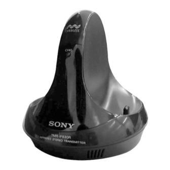
TMR-IF630R is the component model block one in the MDR-IF630RK.
COMPONENT MODEL NAME FOR MDR-IF630RK
Headphones
MDR-IF630R
Transmitter
TMR-IF630R
TMR-IF630R
SPECIFICATIONS
General
Modulation system Frequency modulation
Carrier frequency
Right 2.8 MHz
Left 2.3 MHz
Transmitter
Power source
DC IN 9V jack accepts power supplied from the
AC power adaptor for use on the following voltages:
Where purchased
Operating voltage
U.S.A.
120 V AC, 60 Hz
U.K.
220 – 230 V AC, 50 Hz
European countries
220 – 230 V AC, 50 Hz
Japan (except for Japanese 110 V/120 V/220 V/240V AC, 50/60 Hz
domestic model)
Other countries
220 – 230 V AC, 50/60Hz or
120 V AC, 60 Hz
Audio input
Phono jacks/stereo mini jack
Dimensions
Approx. 130 x 135 x 150 mm
1
3
(5
/
x 5
/
4
8
Mass
Approx. 200 g (7 oz)
Design and specifications are subject to change without notice.
x 6 in) (w/h/d)
US Model
AEP Model
UK Model
E Model
Tourist Model
TRANSMITTER
Advertisement
Table of Contents

Summary of Contents for Sony TMR-IF630R
- Page 1 TMR-IF630R SERVICE MANUAL US Model AEP Model UK Model Ver 1.0 2000.12 E Model Tourist Model TMR-IF630R is the component model block one in the MDR-IF630RK. COMPONENT MODEL NAME FOR MDR-IF630RK Headphones MDR-IF630R Transmitter TMR-IF630R SPECIFICATIONS General Modulation system Frequency modulation Carrier frequency Right 2.8 MHz...
-
Page 2: Section 1 General
SECTION 1 This section is extracted from instruction manual. GENERAL ATT (attenuator) selector Setting up the If a loud sound is distorted when the transmitter is connected to an audio output jack other than transmitter the headphones jack, set the ATT selector on the transmitter to -12 dB. -
Page 3: Section 2 Disassembly
SECTION 2 DISASSEMBLY Note : The equipment can be removed using the following procedure. Cabinet (top) TX BASE board TX LED board Note : Follow the disassembly procedure in the numerical order given. 2-1. CABINET (TOP) 2-2.TX BASE BOARD 3 Cabinet (top) 1 Claw 2 TX BASE board 2 LED board (CN1) -
Page 4: Section 3 Electrical Adjustments
3. L-ch adjustment should be completed before performing R-ch TP11 (L-ch) TP13 (R-ch) adjustment. – 4. Supply 9 V dc to the transmitter section (TMR-IF630R) and 2.4 V dc to the headphones section (MDR-IF630R) as the power TP15 (GND) voltage. TRANSMITTER SECTION Adjustment Procedure : No signal state. - Page 5 TMR-IF630R SECTION 4 DIAGRAMS 4-1. BLOCK DIAGRAM IC601 RV51 ALC AMP. COMPRESSOR RF LEVEL D51,Q51 C60-C62 OUT2 INPUT L-CH OSCILLATOR/ BUFFER LED DRIVE AUDIO MODULATOR (IR LED) VREF G.CELL LED DRIVE OUT1 2.3MHz 3 13 OSC COIL IC602 (CHG) COMPRESSOR...
- Page 6 TMR-IF630R 4-2. SCHEMATIC DIAGRAM –MAIN SECTION– • See page 11 for IC Block Diagrams. Note on Schematic Diagram: • All capacitors are in µF unless otherwise noted. pF: µµF 50 WV or less are not indicated except for electrolytics and tantalums.
- Page 7 TMR-IF630R 4-3. PRINTED WIRING BOARD –MAIN SECTION– • Semiconductor Location Ref. No. Location D-11 (TP15) D601 D605 (TP11) (TP13) IC601 IC602 IC603 IC604 C-11 MDR-IF630R MDR-IF630R IC 601 IC 602 (BATTERY CHARGER) (BATTERY CHARGER) (TO RIGHT) (IR LED) (TO LEFT)
-
Page 8: Ic Block Diagrams
4-4. IC BLOCK DIAGRAMS IC 601, IC602 TK10690M NF IN INPUT OUTPUT G SELL REF CAP VREF CONT IN RECT RECT CAP IC 603 TB1004AF (EL) 22BIT COUNTER 10 VDD OSC1 TIMER OUT1 OSC2 TIMER OUT2 OSC3 CMP- INITIALIZE CMP+ RESET —... -
Page 9: Section 5 Exploded Views
SECTION 5 EXPLODED VIEWS NOTE: • -XX, -X mean standardized parts, so they may • The mechanical parts with no reference number have some differences from the original one. in the exploded views are not supplied. • Items marked “*” are not stocked since they •... -
Page 10: Section 6 Electrical Parts List
SECTION 6 TX BASE ELECTRICAL PARTS LIST NOTE: • Due to standardization, replacements in the • CAPACITORS: • SEMICONDUCTORS parts list may be different from the parts uF: µF In each case, u: µ, for example: specified in the diagrams or the components •... - Page 11 TX BASE Ref. No. Part No. Description Remarks Ref. No. Part No. Description Remarks < JACK > 1-216-057-00 METAL CHIP 2.2K 1/10W 1-216-097-11 RES-CHIP 100K 1/10W 1-566-822-11 JACK (AUTO IN B) 1-216-089-11 RES-CHIP 1/10W 1-580-441-61 JACK, PIN 2P (AUTO IN A) 1-216-109-00 METAL CHIP 330K 1/10W...
- Page 12 TX BASE TX LED Ref. No. Part No. Description Remarks < VARIABLE RESISTOR > 1-241-762-11 RES, ADJ, CARBON 2.2K RV51 1-241-762-11 RES, ADJ, CARBON 2.2K < SWITCH > 1-771-961-11 SWITCH, SLIDE (INPUT SOURCE) 1-771-961-11 SWITCH, SLIDE (ATT) ************************************************************ 1-679-555-11 TX LED BOARD ************ 3-223-721-01 HOLDER, LED <...
- Page 13 TMR-IF630R Sony Corporation 2000L16023-1 Audio Entertainment Group 9-873-018-11 Printed in Japan © 2000.12 — 16 — Published by General Engineering Dept.


Need help?
Do you have a question about the TMR-IF630R and is the answer not in the manual?
Questions and answers