Advertisement
SERVICE MANUAL
Ver 1.0
1998.06
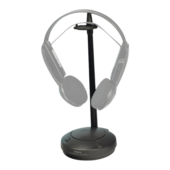
TMR-RF450R is the component model block one in MDR-RF430RK/RF450RK.
COMPONENT MODEL NAME FOR MDR-RF430RK/RF450RK
Wireless Stereo Headphones
Transmitter
MICROFILM
TMR-RF450R
MDR-RF430RK
MDR-RF450RK
MDR-RF430
MDR-RF450
TMR-RF450R
TMR-RF450R
SPECIFICATIONS
General
Carrier frequency
433.40 – 434.40 MHz
Channel
Ch1, Ch2, Ch3
Modulation
FM stereo
Frequency response 20 – 20,000Hz (MDR-RF430RK)
18 – 22,000Hz (MDR-RF450RK)
Transmitter
Power source
DC 9V : supplied AC power adaptor
Audio input
Phono jacks / stereo mini jack
Dimensions
Approx. 120 mm dia x 290 mm
(4
3
/
x 11
1
/
4
2
Mass
Approx. 155g (5.5oz.)
Design and specifications are subject to change without notice.
in.) (w/h)
RF STEREO TRANSMITTER
AEP Model
Advertisement
Table of Contents

Related Manuals for Sony TMR-RF450R


Summary of Contents for Sony TMR-RF450R
-
Page 1: Service Manual
TMR-RF450R SERVICE MANUAL AEP Model Ver 1.0 1998.06 TMR-RF450R is the component model block one in MDR-RF430RK/RF450RK. COMPONENT MODEL NAME FOR MDR-RF430RK/RF450RK MDR-RF430RK MDR-RF450RK Wireless Stereo Headphones MDR-RF430 MDR-RF450 Transmitter TMR-RF450R TMR-RF450R SPECIFICATIONS General Carrier frequency 433.40 – 434.40 MHz... -
Page 2: Section 1 Disassembly
SECTION 1 DISASSEMBLY Note : Follow the disassembly procedure in the numerical order given. 1-1. TX BOARD REMOVAL Cabinet (Upper) VCO board ANT board 7 Remove solder TX board 6 Remove solder 5 TX shield plate Cabinet (Lower) 1 Screws +P 2x10 –... -
Page 3: Electrical Adjustments
Headphones 5. Set the TX board L-ch (J403) input to OFF (not doing so will MDR-RF430 cause modulation in the sub-carrier, preventing correct measure- TMR-RF450R ment) MDR-RF450 6. Check to make sure the frequency counter reading is 48 –52kHz. Setting : If the measured value is other than the specified value, adjust the frequency to 50kHz by turning the RV405 on the TX board. - Page 4 Connection points : [ TX BOARD ] (Conductor side) digital voltmeter (AC range) oscilloscope frequency counter Adjustment Location : [TX BOARD] (Component side) J402 J403 (R-CH) (L-CH) S402 Channel Select Switch S401 Noise Filter ON/OFF Switch RV402 (L-CH) Send Frequency Adjustment RV403 (R-CH) RV404 : Main Carrier...
-
Page 7: Section 4 Exploded View
SECTION 4 EXPLODED VIEW NOTE : • -XX, -X mean standardized parts, so they • The mechanical parts with no reference may have some difference from the original number in the exploded views are not one. supplied. • Items marked “ * ”are not stocked since they are seldom required for routine service. - Page 8 SECTION 5 ELECTRICAL PARTS LIST NOTE : • Due to standardization, replacements in the • Items marked “ * ”are not stocked since they When indicating parts by reference num- parts list may be different from the parts are seldom required for routine service. Some ber, please include the board.
- Page 9 Ref. No. Part No. Description Remark Ref. No. Part No. Description Remark Q404 8-729-045-00 TRANSISTOR SBX1639-02 R455 1-216-057-00 METAL CHIP 2.2K 1/10W Q405 8-729-045-02 TRANSISTOR KTC3200GR-AT R456 1-216-057-00 METAL CHIP 2.2K 1/10W Q406 8-729-045-00 TRANSISTOR SBX1639-02 R457 1-216-025-91 RES,CHIP 1/10W R458 1-216-085-00 METAL CHIP 1/10W...
- Page 10 TMR-RF450R Sony Corporation 98F027539-1 Printed in Hungary © 1998.6 9-924-919-11 Personal A&V Products Company Published by Quality Engineering Dept. – 12 – (Shibaura)
Need help?
Do you have a question about the TMR-RF450R and is the answer not in the manual?
Questions and answers