Table of Contents
Advertisement
Quick Links
TMR-RF915R/RF945R
QQ
3 7 63 1515 0
SERVICE MANUAL
Ver 1.0 2001. 05
TMR-RF915R is the component model block one in the MDR-RF915RK.
TMR-RF945R is the component model block one in the MDR-RF945RK.
COMPONENT MODEL NAME FOR MDR-RF915RK/
MDR-RF945RK
Wireless Stereo Headphones MDR-RF915R
TE
L 13942296513
Transmitter
www
.
Sony Corporation
9-873-139-11
Personal Audio Company
2001E0200-1
Shinagawa Tec Service Manual Production Group
© 2001.5
http://www.xiaoyu163.com
MDR-RF915RK MDR-RF945RK
MDR-RF945
TMR-RF915R
TMR-RF945
General
Carrier frequency
Channel
Modulation
Frequency response
Transmitter
Power source
Audio input
Dimensions
Mass
Design and specifications are subject to change without
notice.
x
ao
u163
y
i
http://www.xiaoyu163.com
2 9
8
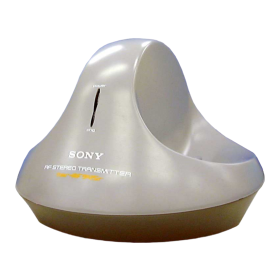
Photo : TMR-RF945R
Q Q
3
6 7
1 3
1 5
SPECIFICATIONS
913.5 – 914.5 MHz
Ch1, Ch2, Ch3
FM stereo
20 – 20,000 Hz
DC 9 V: supplied AC power
adaptor
phono jacks/stereo mini jack
Approx. 150 mm dia
108 mm
X
1
(6
4
/
in.) (w/h)
X
3
Approx. 190 g (6.7 oz.)
co
.
9 4
2 8
US Model
Canadian Model
0 5
8
2 9
9 4
2 8
m
TRANSMITTER
9 9
9 9
Advertisement
Table of Contents

Related Manuals for Sony TMR-RF915R


Summary of Contents for Sony TMR-RF915R
-
Page 1: Service Manual
SERVICE MANUAL US Model Canadian Model Ver 1.0 2001. 05 Photo : TMR-RF945R TMR-RF915R is the component model block one in the MDR-RF915RK. TMR-RF945R is the component model block one in the MDR-RF945RK. COMPONENT MODEL NAME FOR MDR-RF915RK/ MDR-RF945RK MDR-RF915RK MDR-RF945RK... -
Page 2: Table Of Contents
TMR-RF915R/RF945R SECTION 1 GENERAL 3 7 63 1515 0 This section is extracted from TABLE OF CONTENTS instruction manual. Specifications ................1 Setting up the 1. GENERAL ..............2 transmitter 2. DISASSEMBLY 2-1. Cabinet (Upper) ............3 Connect the transmitter to audio/video 2-2. -
Page 3: Disassembly
TMR-RF915R/RF945R SECTION 2 3 7 63 1515 0 DISASSEMBLY • This set can be disassembled in the order shown below. 2-1. CABINET (UPPER) Cabinet (upper) L 13942296513 1 Four screws (P 2 × 8) 2-2. TX-BASE BOARD 2 TX-BASE board... -
Page 4: Electrical Adjustments
TMR-RF915R/RF945R SECTION 3 ELECTRICAL ADJUSTMENTS 3 7 63 1515 0 Setting : Pilot signal Modulation Check and Adjustment 1. Set the channel to CH2. AF signal 2. An electric wave is output for 5or 10 minutes when OFF to ON a generator power supply (Power indicator will ON). -
Page 5: Diagrams
TMR-RF915R/RF945R SECTION 4 DIAGRAMS 3 7 6 3 1 5 1 5 0 4-1. BLOCK DIAGRAMS TX-BASE BOARD IC403 ANT401 STEREO MPX RV403 IC401 MODULATION R-CH J401 BUFFER MOD IN TIME DEVISION AUDIO IN J402 R-CH VCO401 NOISE (VCO UNIT) -
Page 6: Schematic Diagram
TMR-RF915R/RF945R 4-2. SCHEMATIC DIAGRAM • See pa ge 7 for Notes. 3 7 6 3 1 5 1 5 0 1 3 9 4 2 2 9 6 5 1 3 w w w u 1 6 3 http://www.xiaoyu163.com... -
Page 7: Printed Wiring Board
TMR-RF915R/RF945R 4-3. PRINTED WIRING BOARD 3 7 6 3 1 5 1 5 0 ANT401 ANTENNA AUDIO IN DC IN 9V TX-BASE BOARD S402 S401 CHANNEL NOISE FILTER 1t 2 t 3 OFF T ON • Semiconductor Location Ref. No. -
Page 8: Exploded Views
TMR-RF915R/RF945R SECTION 5 EXPLODED VIEWS 3 7 63 1515 0 NOTE: • The mechanical parts with no reference number • -XX, -X mean standardized parts, so they may in the exploded views are not supplied. have some differences from the original one. -
Page 9: Electrical Parts List
TMR-RF915R/RF945R SECTION 6 TX-BASE ELECTRICAL PARTS LIST 3 7 63 1515 0 Ref. No. Part No. Description Remarks Ref. No. Part No. Description Remarks NOTE: • Due to standardization, replacements in the • CAPACITORS: • SEMICONDUCTORS uF: µF parts list may be different from the parts In each case, u: µ, for example:... - Page 10 TMR-RF915R/RF945R TX-BASE 3 7 63 1515 0 Ref. No. Part No. Description Remarks Ref. No. Part No. Description Remarks Q405 8-729-045-00 TRANSISTOR KTA1266GR-AT R483 1-216-057-00 METAL CHIP 2.2K 1/10W Q406 8-729-200-72 TRANSISTOR 2SC2712L-TE85L R484 1-216-052-00 METAL CHIP 1.3K 1/10W...
- Page 11 TMR-RF915R/RF945R 3 7 63 1515 0 L 13942296513 u163 http://www.xiaoyu163.com...
- Page 12 TMR-RF915R/RF945R 3 7 63 1515 0 REVISION HISTORY Clicking the version allows you to jump to the revised page. Also, clicking the version at the upper right on the revised page allows you to jump to the next revised page.
Need help?
Do you have a question about the TMR-RF915R and is the answer not in the manual?
Questions and answers