Advertisement
Quick Links
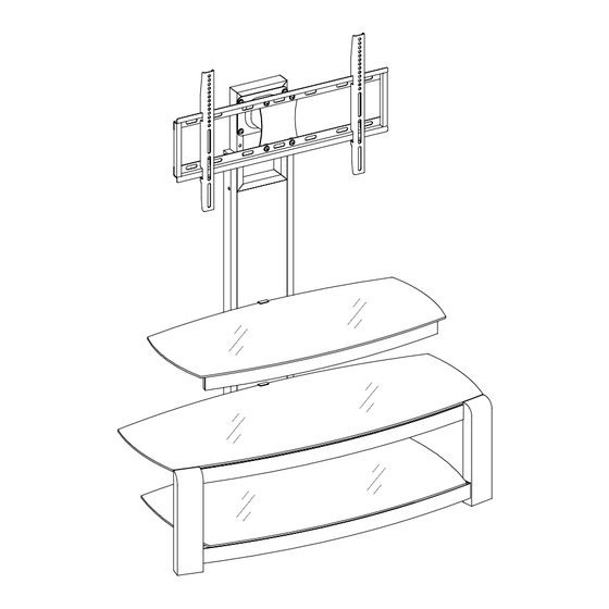
Panel TV Stand
ADULT ASSEMBLY REQUIRED
If you have any questions regarding assembly or if parts are missing, DO NOT return this item to
the store where it was purchased. Please call our customer service number and have
your instructions and parts list ready to provide the model name, part name or factory number.
THIS INSTRUCTION BOOKLET CONTAINS IMPORTANT SAFETY INFORMATION.
PLEASE READ AND KEEP FOR FUTURE REFERENCE.
Page 1
LOT NUMBER:
DATE PURCHASED:
/
/
Advertisement

Subscribe to Our Youtube Channel
Related Manuals for Whalen PROEC41-NV


Summary of Contents for Whalen PROEC41-NV
- Page 1 LOT NUMBER: DATE PURCHASED: Panel TV Stand ADULT ASSEMBLY REQUIRED If you have any questions regarding assembly or if parts are missing, DO NOT return this item to the store where it was purchased. Please call our customer service number and have your instructions and parts list ready to provide the model name, part name or factory number.
- Page 2 M A X I M U M R E C O M M E N D E D W E I G H T L O A D S CATALOG: Flat Panel TV Stand MADE IN CHINA FITS UP TO MOST 47” FLAT PANEL TVs MAXIMUM LOAD 135 lb.
- Page 3 Parts and Hardware List Please read completely through the instructions and verify that all listed parts and hardware are present before beginning assembly. A- Left Side Frame (1) B- Right Side Frame (1) C- Back Panel (1) D - Back Top Frame (1) E- Back Bottom Stretcher (1) F- Top Crossbar (1) G- Top Stringer (1)
- Page 4 Parts and Hardware List (1) Suction Cup (2) 5/8” Bolt (3) 3/4” Bolt (4) 1-1/4” Bolt (15+1 extra) (10+1 extra) (8+1 extra) (4+1 extra) (5) 1-5/8” Bolt (6) 2-1/4” Bolt (7) Hex Nut (8) Lock Washer (12+1 extra) (6+1 extra) (8+1 extra) (40+2 extra) (9) Flat Washer (44+2 extra)
- Page 5 Assembly Instructions Flat Washer 1-5/8” Bolt Lock Washer (8 used in this step) (8 used in this step) (8 used in this step) ⑨ ⑧ ⑤ NOTE: Please do not fully tighten all bolts until you finish assembling all parts. Once assembled, go back and fully tighten all bolts.
- Page 6 Assembly Instructions #4 x 10 mm Screw (4 used in this step) ⑩ 2. Pick up the Back Panel (C) and fit it between the front of Left and Right Side Frames (A and B), as shown above. Insert and screw four 10 mm Screws (10) through the corner brackets to secure the Back Panel in place.
- Page 7 Assembly Instructions Flat Washer (2 used in this step) ⑨ Floor Leveler Lock Washer 2-1/4” Bolt (2 used in this step) (2 used in this step) (2 used in this step) ⑥ ⑧ ⑪ 3. Lay down the unit on a level and protective surface, as shown. Screw the Floor Levelers (11) into the front sockets underneath the bottom rail of Left and Right Side Frames (A and B).
- Page 8 Assembly Instructions 1-5/8” Bolt Flat Washer Lock Washer (4 used in this step) (4 used in this step) (4 used in this step) ⑧ ⑨ ⑤ 6. Attach the Middle Crossbar (H) to the middle rail of Left and Right Side Frames (A and B). Tighten the bolts with enclosed M4 Allen Wrench.
- Page 9 Assembly Instructions Flat Washer Lock Washer 5/8” Bolt (6 used in this step) (6 used in this step) (6 used in this step) ⑧ ⑨ ② 8. Align and attach the Stringers (G, I and K) to the end brackets on the front rails of the Side Frames (A and B) respectively, as shown above.
- Page 10 Assembly Instructions 3/4” Bolt (4 used in this step) ③ Flat Washer Lock Washer 1-1/4” Bolt (8 used in this step) (4 used in this step) (8 used in this step) ④ ⑨ ⑧ 9. Stand the last assembly upright. 10.
- Page 11 Assembly Instructions 2-1/4” Bolt (4 used in this step) ⑥ Flat Washer Hex Nut Lock Washer (8 used in this step) (4 used in this step) (8 used in this step) ⑧ ⑦ ⑨ 11. Attach the Swiveling Bracket (Q) to the top of the Back Top Frame (D) with the pivoting bolt head up, as shown.
- Page 12 Assembly Instructions 3/4” Bolt (4 used in this step) ③ Flat Washer Hex Nut Lock Washer (8 used in this step) (4 used in this step) (4 used in this step) ⑧ ⑦ ⑨ 12. Attach the Mounting Frame (R) to the Swiveling Bracket (Q) using four 3/4” Bolts (3) with Washers (8 and 9) and then secure with the Hex Nuts (7).
- Page 13 Mounting Monitor Bracket to a television with a flat back NOTE: For televisions with a curved or recessed back, proceed directly to the next page. 14. Determine the correct diameter of the bolt your TV requires by hand threading them into the threaded inserts on the back of the TV.
- Page 14 Mounting Monitor Bracket to a television with a curved / recess back 16. Determine the correct diameter of the bolt your TV requires by hand threading them into the threaded insert on the back of the TV. If you encounter any resistance, stop immediately. If you are unable to find the correct bolt consult a local hardware store.
- Page 15 Assembly Instructions 18. Once the Monitor Brackets (S) are attached onto the back of television, ask for assistance to lift the television up to attach the Monitor Brackets onto the Mounting Frame (R). Set the hooks of the Monitor Brackets over the Mounting Frame then lower them onto the bars of the Mounting Frame.
- Page 16 Assembly Instructions 5/8” Bolt (4 used in this step) ② 19. Attach 2 Cable Wheels (T) to the backside of the assembled unit with the 5/8” Bolts (2). Tighten the bolts with the enclosed Allen Wrench. 20. The Cable Wheels allow you to organize, route and separate your component cords and cables to minimize tangling and signal interference.
- Page 17 Assembly Instructions Suction Cup (15 used in this step) ① 21. Put the Suction Cups (1) firmly into the top holes on the Crossbars (F, G and H) and the Stringers (I, J and K). TIP: If a suction cup resists insertion, try pressing down on the middle of the cup with the Allen Wrench while twisting it clockwise into the hole.
- Page 18 Assembly Instructions Tools required: Allen Wrench (provided), Phillips screwdriver, Mallet, Power Drill, and 3/8” Drill Bit. 23. Position the assembled console at the desired location against a wall. If necessary, adjust the pre-attached Floor Levelers on the bottom of the Side Frames (A and B) to level the console. 24.
-
Page 19: Care And Maintenance
Care and Maintenance Use a soft, clean cloth that will not scratch the surface when dusting. Use of furniture polish is not necessary. Should you choose to use polish, test first in an inconspicuous area. Using solvents of any kind on your furniture may damage the finish. Never use water to clean your furniture as it may cause damage to the finish. - Page 20 IF YOU NEED TO ORDER REPLACEMENT PARTS, PLEASE USE THE LIST BELOW Flat Panel TV Stand 1-LSF Left Side Frame 15-SB Swiveling Bracket 29-1 1/4B 1-1/4" Bolt 2-RSF Right Side Frame 16-MF Mounting Frame 30-1 5/8B 1-5/8" Bolt 3-BP Back Panel 17-MB Monitor Bracket 31-2 1/4B...
Need help?
Do you have a question about the PROEC41-NV and is the answer not in the manual?
Questions and answers