Advertisement
Quick Links
Doc. No.
78-1445-03
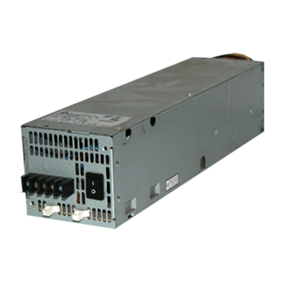
700-Watt DC-Input Power Supply
Installation and Replacement Instructions
Product Number: PWR/7-DC and PWR/7-DC=
This document contains instructions for installing or replacing a direct current (DC)–input power
supply in the Cisco 7000 and Cisco 7507 chassis.
Note
therefore, throughout this document, both chassis are referred to as the chassis, with differences
clearly noted.
The DC-input power supply is optional equipment for the chassis. A second, identical DC-input
power supply, when installed, provides redundant power. In systems with redundant power, the
power supplies are load-sharing and fully hot-swappable; you can remove and replace one supply,
while the remaining supply immediately ramps up to full power to maintain uninterrupted system
operation. Sections in this document include the following:
•
•
Note
system that is already operating. If you are installing a new system, and you ordered a copy, refer to
the Cisco 7000 Hardware Installation and Maintenance or Cisco 7507 Hardware Installation and
Maintenance publications. Because the chassis are shipped without the power supplies installed,
refer to these publications for initial power supply installation and startup procedures. Both of these
publications are also available on UniverCD.
•
•
•
Copyright © 1995
Cisco Systems, Inc.
All rights reserved.
The DC–input power supply installation and functionality are identical for both chassis;
Product Overview, page 2
Installation Safety, ESD Precautions, and Tools Required, page 6
The following section, "Installation," provides instructions for replacing a power supply in a
Installation, page 10
Checking the Installation, page 19
Cisco Information Online, page 35
1
Advertisement

Subscribe to Our Youtube Channel
Related Manuals for Cisco PWR/7-DC Series


Summary of Contents for Cisco PWR/7-DC Series
- Page 1 If you are installing a new system, and you ordered a copy, refer to the Cisco 7000 Hardware Installation and Maintenance or Cisco 7507 Hardware Installation and Maintenance publications. Because the chassis are shipped without the power supplies installed, refer to these publications for initial power supply installation and startup procedures.
- Page 2 A second, identical power supply, if installed, provides redundant power. Power supplies reside in power supply bays in the rear of the router chassis, as shown for the Cisco 7000 in Figure 1 and the Cisco 7507 in Figure 2.
- Page 3 Product Overview Figure 2 DC-Input Power Supplies in Cisco 7507 Captive DO NOT SHIP WITH POWER SUPPLY FASTENER TO BE FULLY ENGAGED INSTALLED BEFORE OPERATING POWER SUPPLY installation screw Upper power supply INPUT VOLTAGE : 40-72 V= INPUT CURRENT : 24-13A...
- Page 4 Product Overview Table 1 lists the DC-input power supply specifications. Table 1 DC-Input Power Supply Specifications Specification Rating DC-input voltage –40 volts (V) minimum –48V nominal –72V maximum DC voltages supplied +5.2V @ 100 amps (A) and steady-state maximum +12V @ 15A current ratings –12V @ 3A +24V @ 5A...
- Page 5 Product Overview The out fail LED lights if the power supply shuts down for either of the following reasons: • Power supply DC-output failure, which could be caused by loss of DC-input power (input line failure or operator turned off system power) or an actual failure in the DC-input power supply •...
- Page 6 Installation Safety, ESD Precautions, and Tools Required Installation Safety, ESD Precautions, and Tools Required Before you begin this installation, review the safety guidelines in this section to avoid injuring yourself or damaging the equipment. This section also provides power requirements to consider if you are adding a second power supply to your system for redundant power, and lists of the tools and parts you need to perform this installation.
- Page 7 If you remove AC-input power supplies from a Cisco 7000 and replace them with Caution DC-input power supplies, you might need to replace the LED board in the Cisco 7000, if the chassis was shipped before November 1, 1994. In this earlier chassis, the LED circuitry will not recognize and indicate the presence of the new DC-input power supplies.
- Page 8 Installation Safety, ESD Precautions, and Tools Required • Do not perform any action that creates a potential hazard to people or makes the equipment unsafe. • Carefully examine your work area for possible hazards such as moist floors, ungrounded power extension cables, and missing safety grounds.
- Page 9 Installation Safety, ESD Precautions, and Tools Required Safety with Electricity You can remove or install a redundant (second) power supply without turning off the other supply. Before removing a redundant power supply, ensure that the first supply is powered on to ensure uninterrupted operation.
- Page 10 Installation • Handle printed circuit boards, such as the arbiter, by the edges only; avoid touching the board components, traces, or connector pins. • Place removed printed circuit boards or components that contain boards on an antistatic surface or in a static shielding bag. Place a removed board component-side-up; place a removed processor module or fan tray board-side-up.
- Page 11 (For the Cisco 7000, refer to Figure 9, and for the Cisco 7507, refer to Figure 10.) This procedure might shift the chassis’ center of gravity toward the front of the rack and Caution may cause the rack or the chassis to tip.
- Page 12 Reconnect all interface cables to the ports on the rear of the chassis. If you completed the Step 10 configuration worksheet before you disconnected the cables, use it as a guideline to reconnect the cables. (For the Cisco 7000, refer to Figure 9, and for the Cisco 7507, refer to Figure 10.) Step 11 Proceed to the section “Checking the Installation”...
- Page 13 Installation Removing a Power Supply If you are replacing the power supply in a single-supply system, remove the existing supply from the lower bay first, if possible, and install the new power supply in the lower bay to maintain a low center of gravity in the chassis.
- Page 14 Installation Use a screwdriver to remove the three power leads from the terminal block. (See Figure 6.) Step 5 Use a screwdriver to reinstall the terminal block cover. (The terminal block cover should Step 6 stay with the power supply.) Do not overtighten the captive installation screws on the terminal block cover.
- Page 15 Installation Grasp the power supply handle and pull the supply out of the bay. Place one hand Step 8 underneath to support the bottom of the supply as you pull it out of the bay. (See Figure 7.) If the power supply resists when you attempt to pull it out of the bay, the switch is probably not fully in the OFF (O) position, or the captive installation screw at the top of the supply is not fully loosened.
- Page 16 If you remove AC-input power supplies from a Cisco 7000 and replace them with Caution DC-input power supplies, you might need to replace the LED board in the Cisco 7000, if the chassis was shipped before November 1, 1994. In this earlier chassis, the LED circuitry will not recognize and indicate the presence of the new DC-input power supplies.
- Page 17 To prevent problems with the Cisco 7000, do not mix DC-input and AC-input power supplies in the same chassis. Your Cisco 7000 must have either DC-input or AC-input power supplies.
- Page 18 Installation The illustration shows the DC power supply terminal block. Wire the DC power supply Warning using the appropriate lugs at the wiring end, as illustrated. The proper wiring sequence is ground to ground, positive to positive (line to L), and negative to negative (neutral to N). Note that the ground wire should always be connected first and disconnected last.
- Page 19 Checking the Installation Do not turn on any power supplies until you are ready to power up the system. The interlock Note switch that locks the power supply in the slot also turns on the system power. If you are installing or replacing a second power supply, repeat step 1 through step 11 for Step 11 the second power supply.
- Page 20 If you are currently using software other than Maintenance Release 9.17(10) or later in your Note Cisco 7000, then the show environment all command will indicate the AC-input power supply as “850W.” A DC-input power supply will still be indicated as “700W.”...
- Page 21 Checking the Installation Figure 9 Cisco 7000 Port Configuration Worksheet SP RP Chassis serial number Slot 0 Slot 1 Slot 2 Slot 3 Slot 4 Circle one: Circle one: Circle one: Circle one: Circle one: AIP/CIP/EIP/FIP/ AIP/CIP/EIP/FIP/ AIP/CIP/EIP/FIP/ AIP/CIP/EIP/FIP/ AIP/CIP/EIP/FIP/...
- Page 22 Checking the Installation Figure 10 Cisco 7507 Port Configuration Worksheet Chassis serial number Slot 0 Slot 1 Slot 4 Slot 5 Slot 6 Slot 2 Slot 3 Circle one: Circle one: Circle one: Circle one: Circle one: RSP2 RSP2 AIP/CIP/EIP/FEIP/FIP/...
- Page 23 Translated Safety Warnings Translated Safety Warnings Following are translations of the safety warnings that appear throughout this publication: Chassis Lifting Warning Two people are required to lift the chassis. Grasp the chassis underneath the lower edge Warning and lift with both hands. To prevent injury, keep your back straight and lift with your legs, not your back.
- Page 24 Translated Safety Warnings São necessárias duas pessoas para levantar o chassis. Agarre o chassis imediatamente abaixo Aviso da margem inferior, e levante-o com ambas as mãos. Para evitar lesões, mantenha as suas costas direitas e levante o peso com ambas as pernas, sem forçar as costas. Para prevenir danos no chassis e nos seus componentes, nunca tente levantá-lo pelas asas das unidades abastecedoras de energia, nem pelos processadores de interface, ou pelos painéis plásticos localizados na frente do chassis.
- Page 25 Translated Safety Warnings U dient de voeding niet aan te raken zolang het netsnoer aangesloten is. Bij Waarschuwing systemen met een stroomschakelaar zijn er lijnspanningen aanwezig in de voeding, zelfs wanneer de stroomschakelaar uitgeschakeld is en het netsnoer aangesloten is. Bij systemen zonder een stroomschakelaar zijn er lijnspanningen aanwezig in de voeding wanneer het netsnoer aangesloten Älä...
- Page 26 Translated Safety Warnings Voordat u aan een frame of in de nabijheid van voedingen werkt, dient u bij Waarschuwing wisselstroom toestellen de stekker van het netsnoer uit het stopcontact te halen; voor gelijkstroom toestellen dient u de stroom uit te schakelen bij de stroomverbreker. Kytke irti vaihtovirtalaitteiden virtajohto ja katkaise tasavirtalaitteiden virta Varoitus suojakytkimellä, ennen kuin teet mitään asennuspohjalle tai työskentelet virtalähteiden...
- Page 27 Translated Safety Warnings Denne enheten kan være utstyrt med mer enn én strømledning. Koble fra de to Advarsel strømledningene før det utføres reparasjonsarbeid på enheten for å redusere faren for elektriske støt. Esta unidade poderá ter mais do que um cabo de alimentação. Para reduzir o risco de choque Aviso eléctrico, desligue os dois cabos de alimentação antes de efectuar reparações na unidade.
- Page 28 Translated Safety Warnings Når denne enheten installeres, må alle kraftledninger sikres for å unngå at Advarsel feltkabelkoblingene forstyrres. Para evitar problemas com as ligações de rede de campanha, prenda todos os cabos de Aviso corrente quando instalar esta unidade. Sujetar todo el cableado de alimentación cuando se instale este equipo para evitar ¡Advertencia! que se mezcle con las conexiones del cableado "in situ".
- Page 29 Translated Safety Warnings Tämä tuote on riippuvainen rakennukseen asennetusta oikosulkusuojauksesta Varoitus (ylivirtasuojauksesta). Varmista, että vaihevirtajohtimissa (kaikissa virroitetuissa johtimissa) käytetään Yhdysvalloissa alle 120 voltin, 30 ampeerin ja monissa muissa maissa 240 voltin, 20 ampeerin sulaketta tai suojakytkintä. Attention Pour ce qui est de la protection contre les courts-circuits (surtension), ce produit dépend de l'installation électrique du local.
- Page 30 Translated Safety Warnings Avant de pratiquer l'une quelconque des procédures ci-dessous, vérifier que le circuit en Attention courant continu n'est plus sous tension. Pour en être sûr, localiser le disjoncteur situé sur le panneau de service du circuit en courant continu, placer le disjoncteur en position fermée (OFF) et, à l'aide d'un ruban adhésif, bloquer la poignée du disjoncteur en position OFF.
- Page 31 Translated Safety Warnings In fase di installazione dell'unità, eseguire sempre per primo il collegamento a massa Avvertenza e disconnetterlo per ultimo. Når enheten installeres, må jordledningen alltid tilkobles først og frakobles sist. Advarsel Ao instalar a unidade, a ligação à terra deverá ser sempre a primeira a ser ligada, e a última Aviso a ser desligada.
- Page 32 Translated Safety Warnings När flertrådiga ledningar krävs måste godkända ledningskontakter användas, t.ex. Varning! kabelsko av sluten eller öppen typ med uppåtvänd tapp. Storleken på dessa kontakter måste vara avpassad till ledningarna och måste kunna hålla både isoleringen och ledaren fastklämda. DC Power Disconnection Warning Before performing any of the following procedures, ensure that power is removed from Warning...
- Page 33 Translated Safety Warnings Innan du utför någon av följande procedurer måste du kontrollera att strömförsörjningen Varning! till likströmskretsen är bruten. Kontrollera att all strömförsörjning är BRUTEN genom att slå AV det överspänningsskydd som skyddar likströmskretsen och tejpa fast överspänningsskyddets omkopplare i FRÅN-läget. DC Power Supply Wiring Warning The illustration shows the DC power supply terminal block.
- Page 34 Translated Safety Warnings tierra, positivo con positivo (la línea con la L) y negativo con negativo (el neutro con la N). Tenga en cuenta que el conductor de tierra siempre tiene que conectarse el primero y desconectarse el último. Illustrationen visar anslutningsplinten för likströmförsörjningsenheten. Koppla Varning! ledningarna till strömförsörjningsenheten med lämpliga kabelskor i ledningsändarna som bilden visar.
- Page 35 LAN/X.25, Point and Click Internetworking, RouteStream, SMARTnet, SwitchProbe, SynchroniCD, The Cell, VirtualStream, WNIC, Workgroup Director, Workgroup Stack, and XCI are trademarks, Access by Cisco and Bringing the power of internetworking to everyone are service marks, and Cisco, Cisco Systems, the Cisco Systems logo, EtherSwitch, IGRP, Kalpana, LightStream, and UniverCD are registered trademarks of Cisco Systems, Inc. All other trademarks, service marks, registered trademarks, or registered service marks mentioned in this document are the property of their respective owners.
Need help?
Do you have a question about the PWR/7-DC Series and is the answer not in the manual?
Questions and answers