Table of Contents
Advertisement
Quick Links
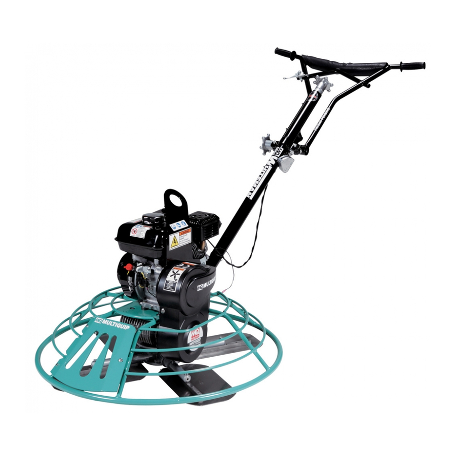
OPERATION MANUAL
MODEL J36E2
WALK-BEHIND TROWEL
(2 HP 230 VAC ELECTRIC MOTOR)
S/N LE0118040 AND ABOVE
Revision #3 (08/26/19)
To find the latest revision of this publication or
associated parts manual, visit our website at:
www.multiquip.com
THIS MANUAL MUST ACCOMPANY THE EQUIPMENT AT ALL TIMES.
PN: 30573
Advertisement
Table of Contents

Subscribe to Our Youtube Channel
Related Manuals for MULTIQUIP J36E2


Summary of Contents for MULTIQUIP J36E2
- Page 1 OPERATION MANUAL MODEL J36E2 WALK-BEHIND TROWEL (2 HP 230 VAC ELECTRIC MOTOR) S/N LE0118040 AND ABOVE Revision #3 (08/26/19) To find the latest revision of this publication or associated parts manual, visit our website at: www.multiquip.com THIS MANUAL MUST ACCOMPANY THE EQUIPMENT AT ALL TIMES.
-
Page 2: Silicosis/Respiratory Warnings
NIOSH/MSHA for the materials being used. PAGE 2 — J36E2 ELECTRIC WALK-BEHIND TROWEL • OPERATION MANUAL — REV. #3 (08/26/19) -
Page 3: Table Of Contents
Electric Motor ............14 Setup ..............15 Inspection .............. 16 Operation ............17–19 Options ..............20 Maintenance ............ 21–28 Troubleshooting ............. 29 Electrical Wiring Diagram ........30 J36E2 ELECTRIC WALK-BEHIND TROWEL • OPERATION MANUAL — REV. #3 (08/26/19) — PAGE 3... -
Page 4: Training Checklist
Emergency stop procedures. Startup of machine, applying power. Maintaining a hover. Maneuvering. Pitching. Concrete fi nishing techniques. Shutdown of machine. Lifting of machine. Machine transport and storage. PAGE 4 — J36E2 ELECTRIC WALK-BEHIND TROWEL • OPERATION MANUAL — REV. #3 (08/26/19) -
Page 5: Daily Pre-Operation Checklist
Daily Pre-Operation Checklist Gearbox oil level Condition of blades Blade pitch operation Safety stop switch operation Main ON/OFF switch operation J36E2 ELECTRIC WALK-BEHIND TROWEL • OPERATION MANUAL — REV. #3 (08/26/19) — PAGE 5... -
Page 6: Safety Information
Crush hazards Indicates a hazardous situation which, if not avoided, COULD result in MINOR or MODERATE INJURY. NOTICE Respiratory hazards Addresses practices not related to personal injury. PAGE 6 — J36E2 ELECTRIC WALK-BEHIND TROWEL • OPERATION MANUAL — REV. #3 (08/26/19) - Page 7 On Quick Pitch models make sure T-Handle latch is locked (engaged). WARNING Training This machine to be operated by qualified personnel only. Ask for training as needed. J36E2 ELECTRIC WALK-BEHIND TROWEL • OPERATION MANUAL — REV. #3 (08/26/19) — PAGE 7...
- Page 8 „ No one other than the operator is to be in the working area when the equipment is in operation. „ DO NOT use the equipment for any purpose other than its intended purposes or applications. PAGE 8 — J36E2 ELECTRIC WALK-BEHIND TROWEL • OPERATION MANUAL — REV. #3 (08/26/19)
- Page 9 Association of Equipment Manufacturers (AEM) can be obtained for a fee by ordering through their website at www.aem.org. Order FORM PT-160 J36E2 ELECTRIC WALK-BEHIND TROWEL • OPERATION MANUAL — REV. #3 (08/26/19) — PAGE 9...
- Page 10 „ Use adequate lifting cable (strap or rope) of suffi cient strength. „ DO NOT lift the machine to unnecessary heights. „ ALWAYS tie down the equipment during transport by securing the equipment. PAGE 10 — J36E2 ELECTRIC WALK-BEHIND TROWEL • OPERATION MANUAL — REV. #3 (08/26/19)
-
Page 11: Specifications
Rotor – RPM (Dry Concrete) 30–160 Insulation Class Operating Weight – lb. (kg) 166 (75) Ambient Temperature 104°F (40°C) Shipping Weight – lb. (kg) 191 (86) J36E2 ELECTRIC WALK-BEHIND TROWEL • OPERATION MANUAL — REV. #3 (08/26/19) — PAGE 11... -
Page 12: General Information
V-belt pulley drive system. The pulley engages using a centrifugal clutch. See the parts section of this manual for a breakdown of the drive system. PAGE 12 — J36E2 ELECTRIC WALK-BEHIND TROWEL • OPERATION MANUAL — REV. #3 (08/26/19) -
Page 13: Components
For the wiring configuration, refer to the 6. Adjustment Knob — Adjust this knob to vary blade Electrical Wiring Diagram section of this manual. speed. J36E2 ELECTRIC WALK-BEHIND TROWEL • OPERATION MANUAL — REV. #3 (08/26/19) — PAGE 13... -
Page 14: Electric Motor
ON/OFF lever switch located on Motor Voltage (15.24 m) (22.86 m) (30.48 m) (60.96 m) the handlebar. 2.0 hp 230 VAC No. 14 No. 12 No. 10 No. 8 PAGE 14 — J36E2 ELECTRIC WALK-BEHIND TROWEL • OPERATION MANUAL — REV. #3 (08/26/19) -
Page 15: Setup
BLADE PITCH CABLE YOKE YOKE EYELET BRASS SET BRASS SET NUT #2 NUT #1 Figure 7. Pitch Cable Yoke Attachment J36E2 ELECTRIC WALK-BEHIND TROWEL • OPERATION MANUAL — REV. #3 (08/26/19) — PAGE 15... -
Page 16: Inspection
Refer to the Maintenance section of this manual for the blade pitch adjustment procedure. Replace any worn blades. PAGE 16 — J36E2 ELECTRIC WALK-BEHIND TROWEL • OPERATION MANUAL — REV. #3 (08/26/19) -
Page 17: Operation
5. Release the lever and verify that the blades stop rotating. could be caused by a dropped trowel. 6. To begin troweling, squeeze and hold the operator presence lever switch. To stop troweling, release the lever. J36E2 ELECTRIC WALK-BEHIND TROWEL • OPERATION MANUAL — REV. #3 (08/26/19) — PAGE 17... - Page 18 160 rpm. Turn the speed control knob clockwise to decrease the blade speed down to a minimum of 30 rpm. PAGE 18 — J36E2 ELECTRIC WALK-BEHIND TROWEL • OPERATION MANUAL — REV. #3 (08/26/19)
- Page 19 ALWAYS stay clear of rotating or moving parts while NEVER place your feet or hands inside the guard rings operating this equipment. while starting or operating this equipment. J36E2 ELECTRIC WALK-BEHIND TROWEL • OPERATION MANUAL — REV. #3 (08/26/19) — PAGE 19...
-
Page 20: Options
(P/N 1817) is available for consistent adjustment of all trowel arms. See Figure 18. Figure 15. Finish Blade Figure 18. Trowel Arm Adjustment Tool PAGE 20 — J36E2 ELECTRIC WALK-BEHIND TROWEL • OPERATION MANUAL — REV. #3 (08/26/19) -
Page 21: Maintenance
3. If the V-belt exhibits any of the above wear conditions replace the V-belt immediately. J36E2 ELECTRIC WALK-BEHIND TROWEL • OPERATION MANUAL — REV. #3 (08/26/19) — PAGE 21... - Page 22 Ideally, a 5 ft. × 5 ft. (1.5 m × 1.5 m), 3/4-inch-thick, flat steel plate should be used. PAGE 22 — J36E2 ELECTRIC WALK-BEHIND TROWEL • OPERATION MANUAL — REV. #3 (08/26/19)
- Page 23 Figure 23 illustrates incorrect spider plate alignment due LOWER WEAR PLATE to improper adjustment, worn spider bushings, or bent SET SCREW trowel arms. (CONE POINT SQ.HD.) SPIDER PLATE Figure 24. Spider Removal J36E2 ELECTRIC WALK-BEHIND TROWEL • OPERATION MANUAL — REV. #3 (08/26/19) — PAGE 23...
- Page 24 3. Wire brush and remove all concrete and debris from all six sides of each of the four trowel arms. This is important to properly seat the new blades. PAGE 24 — J36E2 ELECTRIC WALK-BEHIND TROWEL • OPERATION MANUAL — REV. #3 (08/26/19)
- Page 25 3. A thin shim (Figure 29) may be required to cover the blade holes on the trowel arm. Be sure to align the trowel arm adjustment bolt with the fixture adjustment bolt. J36E2 ELECTRIC WALK-BEHIND TROWEL • OPERATION MANUAL — REV. #3 (08/26/19) — PAGE 25...
- Page 26 Make sure there is little or no Z-clips, and the tie-downs are secured completely over lateral movement between the thrust collar and the the edges of the blade bar. spider shaft. PAGE 26 — J36E2 ELECTRIC WALK-BEHIND TROWEL • OPERATION MANUAL — REV. #3 (08/26/19)
- Page 27 ‘Z’ mounted, with the driving and driven shafts opposed. of the center distance from that listed. The manually controlled pulley must be mounted on the driver shaft. J36E2 ELECTRIC WALK-BEHIND TROWEL • OPERATION MANUAL — REV. #3 (08/26/19) — PAGE 27...
- Page 28 3. Remove the shaft bearing (Figure 33) by removing the retaining ring and pushing against the inside end of the leadscrew in an arbor press. PAGE 28 — J36E2 ELECTRIC WALK-BEHIND TROWEL • OPERATION MANUAL — REV. #3 (08/26/19)
-
Page 29: Troubleshooting
Check to ensure that each blade is adjusted to Blade Pitch? have the same pitch as all other blades. Adjust per maintenance section in manual. J36E2 ELECTRIC WALK-BEHIND TROWEL • OPERATION MANUAL — REV. #3 (08/26/19) — PAGE 29... -
Page 30: Electrical Wiring Diagram
GROUND CONNECT GREEN GREEN WIRE FROM THE SWITCH BOX IS TERMINATED ON THE GROUND TERMINAL WIRE TO SCREW INSIDE THE MICRO-SWITCH HOUSING. AT ON/OFF SWITCH BOX. PAGE 30 — J36E2 ELECTRIC WALK-BEHIND TROWEL • OPERATION MANUAL — REV. #3 (08/26/19) - Page 31 NOTES J36E2 ELECTRIC WALK-BEHIND TROWEL • OPERATION MANUAL — REV. #3 (08/26/19) — PAGE 31...
- Page 32 © COPYRIGHT 2019, MULTIQUIP INC. Multiquip Inc , the MQ logo are registered trademarks of Multiquip Inc. and may not be used, reproduced, or altered without written permission. All other trademarks are the property of their respective owners and used with permission.
Need help?
Do you have a question about the J36E2 and is the answer not in the manual?
Questions and answers