Table of Contents
Advertisement
Quick Links
Advertisement
Chapters
Table of Contents

Related Manuals for Komatsu Galeo BR380JG-1


Summary of Contents for Komatsu Galeo BR380JG-1
- Page 1 https://tractormanualz.com...
- Page 2 https://tractormanualz.com 1 - 1...
-
Page 3: Foreword
Keep this manual in the storage location for the operation and maintenance manual given below, and have all personnel read it periodically. If this manual has been lost or has become dirty and cannot be read, request a replacement manual immediately from Komatsu or your Komatsu distributor. - Page 4 FOREWORD FOREWORD https://tractormanualz.com 1 - 3...
- Page 5 FOREWORD FOREWORD https://tractormanualz.com 1 - 4...
-
Page 6: Safety Information
FOREWORD SAFETY INFORMATION SAFETY INFORMATION To enable you to use this machine safely, safety precautions and labels are given in this manual and affixed to the machine to give explanations of situations involving potential hazards and of the methods of avoiding such situations. - Page 7 Continuing improvements in the design of this machine can lead to changes in detail which may not be reflected in this manual. Consult Komatsu or your Komatsu distributor for the latest available information of your machine or for questions regarding information in this manual.
-
Page 8: Introduction
BREAKING IN THE NEW MACHINE NOTICE Your Komatsu machine has been thoroughly adjusted and tested before shipment from the factory. However, operating the machine under full load before breaking the machine in can adversely affect the performance and shorten the machine life. -
Page 9: Necessary Information
FOREWORD NECESSARY INFORMATION NECESSARY INFORMATION When requesting service or ordering replacement parts, please inform your Komatsu distributor of the following items. PRODUCT IDENTIFICATION NUMBER (PIN)/MACHINE SERIAL NO. PLATE Provided at the rear on the right side of the frame. The design of the nameplate differs according to the territory. -
Page 10: Position Of Service Meter
FOREWORD NECESSARY INFORMATION POSITION OF SERVICE METER Provided above the machine monitors on the control panel. TABLE OF ENTER SERIAL NO. AND DISTRIBUTOR Machine serial No. Engine serial No. Product identification number (PIN) Distributor name Address Service Personnel Phone/Fax https://tractormanualz.com 1 - 9... -
Page 11: Table Of Contents
FOREWORD CONTENTS CONTENTS FOREWORD FOREWORD SAFETY INFORMATION INTRODUCTION FRONT/REAR, LEFT/RIGHT DIRECTIONS OF MACHINE BREAKING IN THE NEW MACHINE NECESSARY INFORMATION PRODUCT IDENTIFICATION NUMBER (PIN)/MACHINE SERIAL NO. PLATE ENGINE SERIAL NO. PLATE AND POSITION POSITION OF SERVICE METER TABLE OF ENTER SERIAL NO. AND DISTRIBUTOR SAFETY SAFETY SAFETY LABELS... - Page 12 PRIMARY CONVEYOR RELATED PARTS 4- 12 RECOMMENDED FUEL, COOLANT AND LUBRICANTS 4- 13 RECOMMENDED BRANDS, RECOMMENDED QUALITY FOR PRODUCTS OTHER THAN KOMATSU GENUINE OIL 4- 15 STANDARD TIGHTENING TORQUES FOR BOLTS AND NUTS 4- 16 CRUSHER ACCESSORY TOOLS 4- 16...
- Page 13 FOREWORD CONTENTS SERVICE PROCEDURE 4- 22 INITIAL 250 HOURS SERVICE (FIRST MAINTENANCE FOR NEW MACHINE ONLY) 4- 22 INITIAL 1000 HOURS SERVICE (FIRST MAINTENANCE FOR NEW MACHINE ONLY) 4- 22 WHEN REQUIRED 4- 23 CHECK BEFORE STARTING 4- 66 EVERY 10 HOURS SERVICE 4- 67 EVERY 100 HOURS SERVICE 4- 68...
- Page 14 FOREWORD CONTENTS HYDRAULIC SECONDARY CONVEYOR 6- 41 SPECIFICATIONS 6- 41 GENERAL VIEW 6- 41 INCLINED LEG CONNECTING METHOD 6- 43 LIFTING METHOD 6- 44 CONNECTING METHOD TO MACHINE BODY 6- 44 PRECAUTIONS ON OPERATION 6- 44 INSPECTION, MAINTENANCE AND ADJUSTMENT 6- 45 TROUBLES AND CORRECTIVE ACTIONS 6- 47...
- Page 15 https://tractormanualz.com 2 - 1...
-
Page 16: Safety
SAFETY SAFETY SAFETY SAFETY LABELS POSITIONS OF SAFETY PICTOGRAMS SAFETY LABELS GENERAL PRECAUTIONS 2- 15 SAFETY RULES 2- 15 IF ABNORMALITIES ARE FOUND 2- 15 CLOTHING AND PERSONAL PROTECTIVE ITEMS 2- 15 FIRE EXTINGUISHER AND FIRST AID KIT 2- 15 SAFETY FEATURES 2- 15 KEEP MACHINE CLEAN... - Page 17 SAFETY SAFETY PRECAUTIONS FOR OPERATION 2- 23 STARTING ENGINE 2- 23 CHECKS BEFORE STARTING ENGINE 2- 23 PRECAUTIONS WHEN STARTING 2- 23 PRECAUTIONS IN COLD AREAS 2- 26 OPERATION 2- 25 CHECK BEFORE OPERATION 2- 25 PRECAUTIONS WHEN CHANGING DIRECTION 2- 25 PRECAUTIONS WHEN TRAVELING 2- 25...
- Page 18 SAFETY SAFETY PRECAUTIONS FOR MAINTENANCE 2- 35 WARNING TAG 2- 35 KEEP WORK PLACE CLEAN AND TIDY 2- 35 APPOINT LEADER WHEN WORKING WITH OTHERS 2- 35 STOP ENGINE BEFORE CARRYING OUT INSPECTION AND MAINTENANCE 2- 35 TWO WORKERS FOR MAINTENANCE WHEN ENGINE IS RUNNING 2- 36 PRECAUTIONS FOR CONVEYOR MAINTENANCE 2- 36...
-
Page 19: Safety Labels
If the labels are damaged, lost, or cannot be read properly, replace them with new ones. For details of the part numbers for the labels, see this manual or the actual label, and place an order with Komatsu distributor. https://tractormanualz.com... -
Page 20: Positions Of Safety Pictograms
SAFETY SAFETY LABELS POSITIONS OF SAFETY PICTOGRAMS https://tractormanualz.com 2 - 6... -
Page 21: Safety Labels
SAFETY SAFETY LABELS SAFETY LABELS (1) Caution when leaving top operating place (8295-93-1371) (2) Caution for electrical wires (8295-93-1580) (3) Caution when operating and performing inspection or maintenance (09651-A0641) https://tractormanualz.com 2 - 7... - Page 22 SAFETY SAFETY SAFETY LABELS SAFETY LABELS (4) Warning when operating (8221-93-1611) (5) Caution for high-temperature coolant, hydraulic oil (09653-A0481) (6) Warning to prevent operator from falling (09805-C0881) https://tractormanualz.com 2 - 8...
- Page 23 SAFETY SAFETY SAFETY LABELS SAFETY LABELS (7) Caution when engine is running (09667-A0481) (8) Caution when handling cable (09808-A0881) (9) Warning when inspecting crusher pulley (09667-A0641) https://tractormanualz.com 2 - 9...
- Page 24 SAFETY SAFETY SAFETY LABELS SAFETY LABELS (10) Caution when inspecting crusher (09838-H1201) (11) Warning about flying rubble (09826-A0881) (12) Prohibition of entry inside operating range (09829-H1681) https://tractormanualz.com 2 - 10...
- Page 25 SAFETY SAFETY SAFETY LABELS SAFETY LABELS (13) Danger around conveyor (09828-H2321) (14) Warning when inspecting conveyor (09667-A0641) (15) Caution when approaching when grizzly feeder is operating (09834-H1201) https://tractormanualz.com 2 - 11...
- Page 26 SAFETY SAFETY SAFETY LABELS SAFETY LABELS (16) Caution when adjusting track tension (09657-A0881) (17) Caution when approaching when magnetic separator is operating (8248-93-1630) (18) Caution when removing steel rods (8240-93-1280) (19) Caution when removing steel rods (8240-93-1290) https://tractormanualz.com 2 - 12...
- Page 27 SAFETY SAFETY SAFETY LABELS SAFETY LABELS (20) Prohibition of jump start (09842-A0481) (21) Caution with high temperatures (09817-A0753) (22) Caution to prevent falling (09805-A0881) https://tractormanualz.com 2 - 13...
- Page 28 SAFETY SAFETY SAFETY LABELS SAFETY LABELS (23) Caution with high magnetic force (09831-H3281) (24) Caution when removing foreign material (8295-93-2840) https://tractormanualz.com 2 - 14...
-
Page 29: General Precautions
SAFETY GENERAL PRECAUTIONS GENERAL PRECAUTIONS SAFETY RULES Only trained and authorized personnel can operate and maintain the machine. Follow all safety rules, precautions and instructions when operating or performing maintenance on the machine. If you are under the influence of alcohol or medication, your ability to safely operate or repair your machine may be severly impaired putting yourself and everyone else on your jobsite in danger. -
Page 30: Keep Machine Clean
SAFETY GENERAL PRECAUTIONS KEEP MACHINE CLEAN If water gets into the electrical system, there is a hazard that it will cause malfunctions or misoperation. Do not use water or steam to wash the electrical system (sensors, connectors). If inspection and maintenance is carried out when the machine is still dirty with mud or oil, there is a hazard that you will slip and fall, or that dirt or mud will get into your eyes. -
Page 31: Handrails And Steps
SAFETY GENERAL PRECAUTIONS HANDRAILS AND STEPS To prevent personal injury caused by slipping or falling off the machine, always do as follows. Use the handrails and steps marked by arrows in the diagram on the right when getting on or off the machine. To ensure safety, always face the machine and maintain three-point contact (both feet and one hand, or both hands and one foot) with the handrails and steps (including the track shoe) -
Page 32: Prevention Of Burns
SAFETY GENERAL PRECAUTIONS PREVENTION OF BURNS Hot coolant To prevent burns from hot water or steam spurting out when checking or draining the coolant, wait for the water to cool to a temperature where it is possible to touch the radiator cap by hand before starting the operation. -
Page 33: Action If Fire Occurs
Any modification made without authorization from Komatsu can create hazards. Before making a modification, consult your Komatsu distributor. Komatsu will not be responsible for any injuries, accidents, product failures or other property damages resulting from modifications made without authorization from Komatsu. -
Page 34: Working On Loose Ground
SAFETY GENERAL PRECAUTIONS WORKING ON LOOSE GROUND Avoid traveling or operating your machine too close to the edge of cliffs, overhangs, and deep ditches. The ground may be weak in such areas. If the ground should collapse under the weight or vibration of the machine, there is a hazard that the machine may fall or tip over. -
Page 35: Ventilation For Enclosed Areas
Always observe the rules and regulations for the work site and environmental standards. This machine does not use asbestos, but there is a danger that imitation parts may contain asbestos, so always use genuine Komatsu parts. https://tractormanualz.com 2 - 21... -
Page 36: Magnetic Separator
SAFETY GENERAL PRECAUTIONS MAGNETIC SEPARATOR (HANGING TYPE) There is a strong magnetic force around the magnetic separator, and this may cause malfunction of pacemakers or other serious injury, so always do as follows when operating this machine (driving, operating, carrying out maintenance, transporting, storing, etc.). -
Page 37: Precautions For Operation
SAFETY PRECAUTIONS FOR OPERATION PRECAUTIONS FOR OPERATION STARTING ENGINE If there is a warning tag on the starting switch, do not start the engine or touch any switch. CHECKS BEFORE STARTING ENGINE Carry out the following checks before starting the engine at the beginning of the day's work. Remove all dirt from the surface of the lens of the front lamps and working lamps, and check that they light up correctly. - Page 38 SAFETY PRECAUTIONS FOR OPERATION If the battery electrolyte is frozen, do not charge the battery or start the engine with a different power source. There is a hazard that this will ignite the battery and cause the battery to explode. Before charging or starting the engine with a different power source, melt the battery electrolyte and check that there is no leakage of electrolyte before starting.
-
Page 39: Operation
SAFETY PRECAUTIONS FOR OPERATION OPERATION CHECK BEFORE OPERATION When carrying out the checks, move the machine to a wide area where there are no obstructions, and operate slowly. Do not allow anyone near the machine. Check that the work equipment, traveling device, etc. work properly. Check for any problem in the sound of the machine, vibration, heat, smell, or gauges;... -
Page 40: Traveling On Slopes
SAFETY PRECAUTIONS FOR OPERATION TRAVELING ON SLOPES When traveling downhill, lower the engine speed, keep the travel lever close to the neutral position, and travel at low speed. Always travel straight up or down a slope. Traveling at an angle or across the slope is extremely dangerous. -
Page 41: Parking Machine
SAFETY PRECAUTIONS FOR OPERATION PARKING MACHINE Park the machine on firm, level ground. Select a place where there is no hazard of falling rocks or landslides, or of flooding if the land is low. When the machine is parked on a public road, put up a warning flag, a fence or any other caution sign as well as install an illumination system to the extent that they do not hinder the traffic, so that other ongoing vehicles can readily spot the machine. -
Page 42: Crushing Operation
SAFETY PRECAUTIONS FOR OPERATION CRUSHING OPERATION When inspecting or cleaning the conveyor or crusher, there is danger of getting caught in the rotating parts. Always stop the conveyor and crusher before starting the operation. CHECKS AROUND MACHINE In consideration of the safety to the neighbourhood, put up a protective screen all around the machine. -
Page 43: Ensure Safety While Operating In Tandem With Hydraulic Excavator
SAFETY PRECAUTIONS FOR OPERATION ENSURE SAFETY WHILE OPERATING IN TANDEM WITH HYDRAULIC EXCAVATOR The operator of this machine is supposed to work in cooperation with the operator of a loading machine like a hydraulic excavator or wheel loader. Hence, for the sake of mutual safety,it is recommended for them to determine common signals beforehand and to follow the advice below in particular. -
Page 44: Emergency Stop To Ward Off Dangers While In Crushing Work
SAFETY PRECAUTIONS FOR OPERATION EMERGENCY STOP TO WARD OFF DANGERS WHILE IN CRUSHING WORK If the operator of the machine feels that there is any abnormality in the machine, or if he feels that there is some danger, he should press the emergency stop switch immediately and stop all operations. REMOVE FOREIGN MATERIAL FROM INSIDE CRUSHER If any lumps of steel or other foreign material are caught inside the crusher, always use the following procedure to carry out operations. -
Page 45: Transportation
PRECAUTIONS FOR OPERATION TRANSPORTATION The machine can be divided into parts for transportation, so when transportating the machine, please contact your Komatsu distributor to have the work carried out. LOADING AND UNLOADING When loading or unloading the machine, mistaken operation may bring the hazard of the machine tipping over or falling, so particular care is necessary. -
Page 46: Battery
SAFETY PRECAUTIONS FOR OPERATION BATTERY BATTERY HAZARD PREVENTION Battery electrolyte contains sulphuric acid, and batteries generate flammable hydrogen gas, which may explode. Mistaken handling can lead to serious injury or fire. For this reason, always observe the following precautions. When working with batteries, always wear safety glasses and rubber gloves. Never smoke or use any flame near the battery. -
Page 47: Starting With Booster Cable
SAFETY PRECAUTIONS FOR OPERATION STARTING WITH BOOSTER CABLE If any mistake is made in the method of connecting the booster cables, it may cause the battery to explode, so always do as follows. Starting the engine using a booster cable has to be conducted by a team of two persons with one taking a position at the operator's platform and the other at the battery. -
Page 48: Towing
SAFETY PRECAUTIONS FOR OPERATION TOWING WHEN TOWING Serious injury or death could result if a disabled machine is towed incorrectly or if there is a mistake in the selection or inspection of the wire rope. For towing method, see "METHOD OF TOWING MACHINE (PAGE 3-134)". Always check that the wire rope used for towing has ample strength for the weight of the machine being towed. -
Page 49: Precautions For Maintenance
SAFETY PRECAUTIONS FOR MAINTENANCE PRECAUTIONS FOR MAINTENANCE WARNING TAG Always attach the "DO NOT OPERATE" warning tag to the work equipment control lever in the operator's cab to alert others that you are performing service or maintenance on the machine. Attach additional warning tags around the machine if Keep this warning tag in the tool box while it is not used. -
Page 50: Two Workers For Maintenance When Engine Is Running
SAFETY SAFETY PRECAUTIONS FOR MAINTENANCE PRECAUTIONS FOR MAINTENANCE Put blocks under the track to prevent the machine from moving. TWO WORKERS FOR MAINTENANCE WHEN ENGINE IS RUNNING To prevent injury, do not carry out maintenance with the engine running. If maintenance must be carried out with the engine running, carry out the operation with at least two workers and do as follows. -
Page 51: Precautions When Carrying Out Maintenance Of Feeder, Crusher
SAFETY PRECAUTIONS FOR MAINTENANCE PRECAUTIONS WHEN CARRYING OUT MAINTENANCE OF FEEDER, CRUSHER There is danger of getting caught in the crusher or the drive parts of the feeder, so always do as follows. When carrying out maintenance of the feeder or crusher, always stop the feeder or crusher, then stop the engine. -
Page 52: Noise
SAFETY PRECAUTIONS FOR MAINTENANCE NOISE When carrying out maintenance of the engine and you are exposed to noise for long periods of time, wear ear covers or ear plugs while working. If the noise from the machine is too loud, it may cause temporary or permanent hearing problems. PRECAUTIONS WHEN USING HAMMER When using a hammer, pins may fly out or metal particles may be scattered. -
Page 53: Do Not Disassemble Recoil Spring
Never attempt to disassemble the recoils spring assembly. It contains a spring under high pressure which serves as a shock absorber for the idler. If it is disassembled by mistake, the spring will fly out and cause serious injury. When it becomes necessary to disassemble it, ask your Komatsu distributor to do the work. https://tractormanualz.com... -
Page 54: Precautions With High-Pressure Oil
If any loose bolts are found, stop work and tighten to the specified torque. If any damaged hoses are found, stop operations immediately and contact your Komatsu distributor. Replace the hose if any of the following problems are found. -
Page 55: Periodic Replacement Of Safety Critical Parts
SAFETY PRECAUTIONS FOR MAINTENANCE PERIODIC REPLACEMENT OF SAFETY CRITICAL PARTS It is recommended to carry out machine refueling, inspection and maintenance works without fail and on a periodic basis so that the machine may be used safely for an extended period of time. Be sure to periodically replace the hoses in particular, which are safety critical parts of the machine. - Page 56 https://tractormanualz.com 3 - 1...
-
Page 57: General View
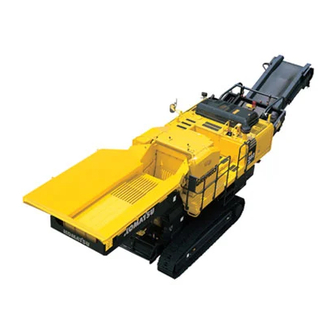
OPERATION GENERAL VIEW GENERAL VIEW GENERAL VIEW OF MACHINE Belt conveyor motor Control box Primary conveyor (10) Sprocket Precleaner (11) Tool box Jaw crusher (12) Grizzly feeder vibrator case Sprinkler (if equipped) (13) Grizzly feeder Hopper (14) Muck discharge conveyor (if equipped) Revolving caution lamp (15) Magnetic separator... -
Page 58: General View Of Controls And Gauges
OPERATION GENERAL VIEW GENERAL VIEW OF CONTROLS AND GAUGES Switches (Main control box and Upper control box) Travel lever lock (17) Grizzly feeder stop switch Travel lever (18) Magnetic separator start switch Horn button (19) Magnetic separator stop switch Engine stop switch (20) Crusher rotation direction selector switch Travel speed selector switch... - Page 59 OPERATION GENERAL VIEW (33) Primary conveyor UP switch/muck discharge (35) Emergency stop switch/actuation selector switch conveyor UP switch (if equipped) (if equipped) (34) Primary conveyor DOWN switch/muck discharge conveyor DOWN switch (if equipped) https://tractormanualz.com 3 - 4...
- Page 60 OPERATION GENERAL VIEW All lighted up screen (in travel mode) Mode monitor (15) Crusher manual normal rotation switch Engine coolant temperature gauge (16) Crusher manual reverse rotation switch Engine coolant temperature monitor (17) Conveyor manual reverse rotation switch Fuel gauge (18) Conveyor manual normal rotation switch Fuel level monitor...
- Page 61 OPERATION GENERAL VIEW Mode monitor Grizzly feeder status lamp Engine coolant temperature gauge Conveyor status lamp Engine coolant temperature monitor (10) Magnetic separator status lamp Fuel gauge (11) Muck discharge conveyor status lamp Fuel level monitor (12) Secondary conveyor status lamp Service meter (13) Vibratory sieve status lamp...
-
Page 62: Explanation Of Components
OPERATION EXPLANATION OF COMPONENTS EXPLANATION OF COMPONENTS The following is an explanation of devices needed for operating the machine. To perform suitable operations correctly and safely, it is important to completely understand methods of operating the equipment, and the meanings of the displays. MACHINE MONITOR Check before starting screen Normal travel screen... - Page 63 OPERATION EXPLANATION OF COMPONENTS BASIC ACTUATION OF MACHINE MONITOR WHEN THERE IS AN ABNORMALITY WHEN STARTING THE ENGINE When in operation mode When in inspection mode When in travel mode If there is any abnormality when starting the engine, the check before starting screen (A) changes to the maintenance interval warning screen (B), warning screen (D), or error screen (E).
- Page 64 OPERATION EXPLANATION OF COMPONENTS After displaying the check before starting screen (A) for 2 seconds, the screen changes to the maintenance interval warning screen (B). After the maintenance time warning screen (B) has been displayed for 30 seconds, the screen will switch to the normal operation screen (C).
- Page 65 OPERATION EXPLANATION OF COMPONENTS BASIC CHECK ITEMS CAUTION These monitors are not provided for the purpose of guaranteeing the conditions of the machine. Do not solely rely on the monitors for the daily inspection, but conduct each specified item of the daily inspection without fail. This displays the basic items that should be checked before starting the engine.
- Page 66 For details of the method of checking the maintenance time, see "MAINTENANCE SCREEN SELECTOR SWITCH (PAGE 3-25)". If it is desired to change the maintenance interval settings, have your Komatsu distributor change the interval settings. https://tractormanualz.com 3 - 11...
- Page 67 OPERATION EXPLANATION OF COMPONENTS CAUTION ITEMS CAUTION When the warning monitor lamp begins to flash or the revolving warning lamp lights up, check and identify the cause in no time. If left unattended for some time, it will lead to a failure. These are items which need to be observed while the engine is running.
- Page 68 OPERATION EXPLANATION OF COMPONENTS FUEL LEVEL MONITOR Monitor (2) lights up to warn the operator the fuel level in the tank is low. If the remaining amount of fuel goes down to 41 liters (10.83 US gal), the light changes from green to red, so add fuel as soon as possible.
- Page 69 OPERATION EXPLANATION OF COMPONENTS EMERGENCY STOP ITEMS CAUTION When this monitor begins to flash or the revolving warning lamp lights up, either stop the engine or reduce the engine speed to low idling immediately, and then check for the trouble spot and take appropriate actions, if necessary. These items must be observed when the engine is running.
- Page 70 OPERATION EXPLANATION OF COMPONENTS ENGINE COOLANT TEMPERATURE MONITOR Monitor (1) warns operator that the engine coolant temperature has risen. If engine coolant temperature becomes abnormally high, monitor lights up red, overheat prevention system is automatically actuated, and the engine speed goes down. Stop operations and run engine at low idle until monitor (1) changes to green.
- Page 71 OPERATION EXPLANATION OF COMPONENTS REMARK Color when the monitor lights up for basic check items, caution items, and emergency stop items are as follows. Color when monitor lights up Type of monitor When When At low normal abnormal temperature Radiator coolant level monitor Engine oil level monitor Maintenance interval monitor Charge monitor...
- Page 72 OPERATION EXPLANATION OF COMPONENTS METER DISPLAY PORTION Normal operation screen (C) Normal inspection screen Normal travel screen Engine pre-heating monitor Fuel gauge Operating mode monitor Hydraulic oil temperature gauge Travel mode monitor Service meter Inspection mode monitor Crusher actual clearance monitor Engine coolant temperature gauge (10) Operating status display lamp...
- Page 73 OPERATION EXPLANATION OF COMPONENTS OPERATING MODE MONITOR This monitor (2) shows that the mode selector switch is at working mode. It is possible to check the operating condition of each piece of work equipment and to identify the work equipment that has suffered excessive load or abnormal load.
- Page 74 OPERATION EXPLANATION OF COMPONENTS METER PORTION ENGINE COOLANT TEMPERATURE GAUGE This meter (5) shows the engine coolant temperature. During operation, the indicator should be in black range (A) to (C). If the indicator enters red range (A) to (B) during operation, the overheat prevention system is actuated.
- Page 75 OPERATION EXPLANATION OF COMPONENTS HYDRAULIC OIL TEMPERATURE GAUGE This meter (7) shows the hydraulic oil temperature. During operation, the indicator should be in black range (A) to (C). If the indicator enters red range (A) during operation, the hydraulic oil temperature is more than 102 °C (215.6 °F). Run the engine at low idling or stop it and wait until the hydraulic oil temperature goes down.
- Page 76 OPERATION EXPLANATION OF COMPONENTS OPERATING STATUS DISPLAY LAMP This lamp (10) display is as shown in the diagram on the right when the working mode is selected with the mode selector switch on the control panel. It is possible to confirm the operating status of each piece of work equipment and to identify the work equipment that has suffered excessive load or abnormal load.
- Page 77 OPERATION EXPLANATION OF COMPONENTS MONITOR SWITCH UNIT Return switch Crusher manual reverse rotation switch UP and numeral input (+) switch (10) Crusher manual normal rotation switch DOWN and numeral input (-) switch (11) Conveyor manual normal rotation switch Input confirmation switch (12) Conveyor manual reverse rotation switch Liquid-crystal monitor adjustment switch...
- Page 78 OPERATION EXPLANATION OF COMPONENTS UP/DOWN SWITCH AND NUMERAL INPUT (+/-) SWITCH 1. These switches (2) and (3) function to move the cursor on the screen display up and down. (2) UP (3) DOWN Each time this switch is pressed, the cursor moves. The screen display is highlighted to match this.
- Page 79 OPERATION EXPLANATION OF COMPONENTS BRIGHTNESS ADJUSTMENT 1. Press either UP switch (2) or DOWN switch (3) to call the brightness adjusting monitor. 2. When the display in the screen is changed to brightness adjusting monitor, press either UP switch (2) or DOWN switch (3) for desired brightness.
- Page 80 OPERATION EXPLANATION OF COMPONENTS MAINTENANCE SCREEN SELECTOR SWITCH Switch (6) is used to check the time remaining until maintenance. When switch (6) is pressed, screen on the monitor display changes to the maintenance screen, as shown in diagram on the right. The time remaining until maintenance is indicated by the color of each monitor display.
- Page 81 Change crusher motor case oil 1000 If it is desired to change settings for the maintenance interval, have your Komatsu distributor change the settings. The method of checking time remaining until maintenance is as follows: 1. Look at the maintenance screen and press the UP switch (2) or DOWN switch (3) on the monitor switches to select the item.
- Page 82 OPERATION OPERATION EXPLANATION OF COMPONENTS EXPLANATION OF COMPONENTS 3. Confirm the time remaining to maintenance. (a): Time remaining to maintenance (b): Initial set time for maintenance When checking only the time remaining to maintenance, press return switch (1) twice. The screen returns to the monitor screen for normal operations.
- Page 83 OPERATION EXPLANATION OF COMPONENTS CRUSHER MANUAL REVERSE ROTATION SWITCH This switch (9) is used during maintenance and inspection of the jaw crusher or to escape from the bridging or blocking condition. It is used when adjusting the discharge port clearance of the jaw crusher, or when carrying out operations to position the flywheel (inching operation).
- Page 84 OPERATION EXPLANATION OF COMPONENTS CRUSHER MANUAL NORMAL ROTATION SWITCH This switch (10) is used during maintenance and inspection of the jaw crusher or to escape from the bridging or blocking condition. The function is the same as the manual reverse rotation switch (9), but when the discharge port of the jaw crusher is clogged with foreign material, this switch can be pressed after stopping the jaw crusher to make it easier to remove the foreign material.
- Page 85 OPERATION EXPLANATION OF COMPONENTS BUZZER CANCEL SWITCH NOTICE If the engine starting switch is turned OFF because some abnormality has been noticed in the machine, and turned ON again, the buzzer sounds, unless that abnormality has not been removed. This switch (13) is used to stop the alarm buzzer when an abnormality has occurred in a warning item during operation of the engine.
- Page 86 OPERATION EXPLANATION OF COMPONENTS FEEDER SPEED SETTING SCREEN SELECTOR SWITCH This switch (15) is used to change the vibration speed of the grizzly feeder and to adjust the feed speed for rubble and rock. When numeral input switch (3) is pressed, the scale goes down in direction (A).
-
Page 87: Switches
OPERATION EXPLANATION OF COMPONENTS SWITCHES Starting switch (13) Magnetic separator start switch Fuel control dial (14) Magnetic separator stop switch Emergency stop switch (15) Jaw crusher start switch Horn button (16) Jaw crusher stop switch Mode selector switch (17) Grizzly feeder start switch Radio controller selector switch (18) Grizzly feeder stop switch... -
Page 88: Starting Switch
OPERATION EXPLANATION OF COMPONENTS STARTING SWITCH Starting switch (1) is used to start or stop the engine. (A): OFF position The starting switch key can be removed, the flow of electricity to the electrical system is cut, and the engine stops. (B): ON position Electricity flows to the charging circuit and lamp circuit. -
Page 89: Emergency Stop Switch
OPERATION EXPLANATION OF COMPONENTS EMERGENCY STOP SWITCH When this switch (3) is pressed, the horn sounds and all the work equipment stops. The engine does not stop. When starting again, first stop the engine, return the emergency stop switch to the OFF position, then start again. When the switch is pressed again, it returns to the OFF position. -
Page 90: Horn Button
OPERATION EXPLANATION OF COMPONENTS HORN BUTTON This switch (4) sounds the horn, when depressed. Be sure to honk it before starting the engine for the purpose of giving warning to those in the surrounding. The horn also sounds under the following conditions. If abnormalities occur at the same time, the horn sounds in the order of priority (1), (2), (3), (4), (5). -
Page 91: Mode Selector Switch
OPERATION EXPLANATION OF COMPONENTS MODE SELECTOR SWITCH CAUTION Stop all the working equipment before operating the mode selector switch. If the mode selector switch is operated while the work equipment is moving, the work equipment makes an emergency stop. This switch (5) is used to switch between travel, work, and inspection. -
Page 92: Lamp Switch
OPERATION EXPLANATION OF COMPONENTS LAMP SWITCH This switch (7) is used to light up the lamps. The panel lamp and working lamp light up. (a) Position 2: Panel lamp and working lamp light up (b) Position 1: Panel lamp lights up (c) OFF position: Lamps are off CRUSHER ROTATION DIRECTION SELECTOR SWITCH This switch (8) is used to select the direction of rotation of the... -
Page 93: Work Equipment Stop Switch
OPERATION EXPLANATION OF COMPONENTS WORK EQUIPMENT STOP SWITCH (1-touch stop switch) For normal operations, use this switch. When this switch (10) is pressed, it is possible to stop the work equipment in turn. The order for starting is as follows. Feeder ->... -
Page 94: Clearance Adjustment Selector Switch
OPERATION EXPLANATION OF COMPONENTS CLEARANCE ADJUSTMENT SELECTOR SWITCH When this switch (19) is operated, it is possible to select the method for adjusting the crusher clearance. (a) A Automatic: The clearance automatically adjusted according to the set value input on the clearance set monitor. - Page 95 OPERATION EXPLANATION OF COMPONENTS CONVEYOR UP/DOWN SWITCH Use these switches to raise or lower the primary conveyor. Switch (23): Raises the conveyor Switch (24): Lowers the conveyor The conveyor raise or lower cylinder is operated only while the switch is being pressed. Switch (25): Emergency stop switch CONVEYOR UP/DOWN SELECTOR SWITCH (Only machines equipped with muck discharge conveyor (if equipped))
-
Page 96: Control Levers
OPERATION EXPLANATION OF COMPONENTS CONTROL LEVERS TRAVEL LEVERS This control lever is used to run the machine. (1) Foreward: Push the control lever forward. (2) Reverse: Pull the lever toward yourself. N Neutral: The machine comes to a halt. When you shift the travel control lever from Neutral to Forward, or from Neutral to Reverse, an alarm begins to sound to caution the people around the machine that it is about to move. -
Page 97: Option-Related Switches
OPERATION EXPLANATION OF COMPONENTS OPTION-RELATED SWITCHES CAUTION The name and panel display for option switches (1) to (6) may differ according to the number and type of options that are connected. In such cases, check the display at the hydraulic pressure pickup port and the panel display to check which switch corresponds to the option before operating. - Page 98 OPERATION EXPLANATION OF COMPONENTS VIBRATORY SIEVE START SWITCH When this switch (5) is pressed, the vibratory sieve is operated and the product discharged from the primary conveyor is sifted and separated. VIBRATORY SIEVE STOP SWITCH When this switch (6) is pressed, the vibratory sieve stops. https://tractormanualz.com 3 - 43...
-
Page 99: Cap, Cover With Lock
OPERATION EXPLANATION OF COMPONENTS CAP, COVER WITH LOCK A lock is provided at the following locations of the machine; the oil filler of the fuel tank, the oil filler of the hydraulic oil tank, the main control box cover, the tool box, the engine hood, the battery box cover and the left and right side doors. - Page 100 OPERATION EXPLANATION OF COMPONENTS METHOD OF OPENING AND CLOSING COVER WITH LOCK TO OPEN THE COVER 1. Insert the key into the key slot. 2. Turn the key counterclockwise and open the cover by pulling the cover grip. (A): Open (B): Lock TO LOCK THE COVER 1.
-
Page 101: Revolving Warning Lamp
OPERATION EXPLANATION OF COMPONENTS REVOLVING WARNING LAMP (Red) The revolving warning lamps light on and off on the following occasions. If abnormalities occur at the same time, the rotating lamp lights up or flashes in the order of priority (1), (2), (3), (4), (5). Abnormality items Rotating lamp displaying When there is abnormality in engine coolant... -
Page 102: Electric Power Takeoff
OPERATION EXPLANATION OF COMPONENTS ELECTRIC POWER TAKEOFF 24 V POWER SOURCE NOTICE Do not use this as the power source for 12 V equipment. It is possible to use the electric power connector (A40) inside the cover at the top of the control box. Capacity: 85 W (24 V x 3.5 A) https://tractormanualz.com 3 - 47... - Page 103 OPERATION EXPLANATION OF COMPONENTS WHEN REMOTE CONTROL IS INSTALLED (If equipped) It is possible to use the power supply socket (1) inside the toolbox on the machine. https://tractormanualz.com 3 - 48...
-
Page 104: Fusible Link
If anything unusual has developed on any of the controllers, do not attempt to overhaul it by yourself, but call your Komatsu distributor for check and repair. Do not open the door inside the main control box in a wet weather condition. -
Page 105: Tool Box
OPERATION EXPLANATION OF COMPONENTS FUSE CAPACITY AND NAME OF CIRCUIT Fuse Name of circuit capacity Key switch Monitor (permanent power source) Spare Spare Controller Solenoid Working lamp Traveling in straight line, 2-stage relief Rotating lamp Electromagnetic valve for attachment, (10) travel alarm (11) Monitor... -
Page 106: Operation
Make a thorough check, and if something unusual is found, be sure to fix it or inform it to the komatsu distributor in your territory. Before starting the engine, walk around the machine and look at the underside of chassis for anything unusual like loose bolts and nuts, leakage of fuel, oil and coolant. - Page 107 OPERATION OPERATION 9. Check of the handrails and steps Check the handrails and steps for any damage or loosened bolts, and repair the damaged part and tighten the loosened bolts, if any. 10. Inspection of damage on the gauges and monitors and looseness of the bolts Inspect if no damage has occurred on the gauges and monitors, and if any abnormality is found, replace it.
- Page 108 OPERATION OPERATION CHECK BEFORE STARTING CHECK COOLANT LEVEL, ADD COOLANT WARNING Do not open the radiator cap unless necessary. Wait for the engine to cool down before checking the coolant in the sub-tank. Immediately after the engine is stopped, the coolant is at a high temperature and the radiator is under high internal pressure. If the cap is removed to check the coolant level in this condition, there is a hazard of burns.
- Page 109 OPERATION OPERATION CHECK OIL LEVEL IN ENGINE OIL PAN, ADD OIL WARNING Parts and oil are at high temperature immediately after the engine is stopped and may cause serious burns. Wait for the oil temperature to go down before performing this operation. 1.
- Page 110 OPERATION OPERATION CHECK FUEL LEVEL, ADD FUEL WARNING When adding fuel, never let the fuel overflow. This may cause a fire. If any fuel is spilled, wipe it up completely. Never bring flames near fuel because it is highly flammable and dangerous. 1.
- Page 111 OPERATION OPERATION CHECK WATER SEPARATOR, DRAIN WATER AND SEDIMENT 1. Open the inspection window in the bottom face of the pump chamber. 2. Inspect the water separator, and check if the ring inside has risen to the marked line. 3. If the ring has risen to the marked line, carry out the procedure from Step 4.
- Page 112 Be sure to check that there are no piles of inflammables on and around the battery and remove them, if any. For the checkup and repairs of troubles in the battery, consult the Komatsu distributor in your territory. CHECK FUNCTION OF HORN 1.
- Page 113 OPERATION OPERATION ADJUSTMENT OF REAR VIEW MIRROR Loosen the bolts securing the square rear view mirror (1) and those securing the round rear view mirror (2), and then adjust the mirror positions so that there will be no blind spot at the rear and left side of the machine and a better view will be available.
- Page 114 OPERATION OPERATION CHECK OF PRIMARY CONVEYOR WARNING When correcting zigzag movement of the primary conveyor, carry that out with the adjust bolts. 1. Foreign materials such as stones, gravel, wire chips, iron and steel bar chips, etc. are likely caught in various parts of the primary conveyor.
- Page 115 OPERATION OPERATION CHECK MAGNETIC SEPARATOR WARNING There is danger that the magnetic field may cause malfunction of pacemakers, so persons wearing pacemakers should not approach within a range of 5 m (16 ft 5 in) from the magnetic separator. The magnetic force will attract metal tools and pieces of steel, and there is danger of getting your fingers or hands caught between such objects and the attracting surface, so do not approach the magnetic separator when carrying metal tools or pieces of steel.
- Page 116 OPERATION OPERATION CAUTION When conduction a trial run of the machine, be sure to run the motor at low speed and check that the conveyor belt does not make a snaky movement. If metal pieces are drawn by the magnetic separator, they will be ejected, accelerated by the metal piece discharging belt. As that poses a big danger, provide a safety cover at the discharging outlet to prevent the metal pieces from flying off.
- Page 117 OPERATION OPERATION ADJUST CLEARANCE FROM CONVEYOR The standard clearance between V-belt surface of the belt conveyor and the magnet is (A), (B) = 350 mm (13.8 in). Change this as necessary according to the condition of the crusher discharge port clearance. Front (P): Change position of magnetic separator chain (1) to adjust, and fit on magnetic separator frame hook (2).
- Page 118 OPERATION OPERATION CHECK OF JAW CRUSHER AND RELATED ACCESSORIES https://tractormanualz.com 3 - 63...
- Page 119 OPERATION OPERATION OPERATION OPERATION Protector bolt (13) Toggle seat Protector (14) Tension spring Cheek plate (15) Lock cylinder Fixed jaw plate wedge bolt (16) Crusher motor Front frame (17) Movable tooth wedge bolt Fixed jaw plate (18) V-belt Crushing chamber (19) Bearing cap tightening bolt Swing jaw plate...
- Page 120 OPERATION OPERATION CAUTION After receiving delivery of a new machine or after turning or replacing the teeth or other wear parts, for the first 50 hours (displayed on the service meter), the settling of mating parts may cause changes in the spring set length and the tightening torque of the nuts and bolts.
- Page 121 OPERATION OPERATION V belt tension adjusting method The V belt tension may be changed by adjusting the turnbuckle located behind the crusher motor. After the adjustment, be sure to tighten the lock nut. 1. Open the V-belt inspection window. 2. Adjust the turnbuckle so that tension load F for one V-belt is 63.6 to 73.6 N {6.5 to 7.5 kgf).
- Page 122 If they do not light up, there is probably a blown bulb or disconnection, so ask your Komatsu distributor to carry out repairs. 4. Insert key into starting switch (2), turn the key to ON position (B), then perform the following checks.
- Page 123 Air cleaner clogging monitor (12) If the monitor does not light up or the buzzer does not sound, the monitor is probably broken, so ask your Komatsu distributor to carry out repairs. 2) After approx. 3 seconds, the screen switches to the normal screen.
- Page 124 OPERATION OPERATION OPERATION OPERATION 3) If the normal screen switches and caution lamp (15) stays lighted up red, carry out inspection immediately of the item where the red lamp is lighted up. 4) If there are any items where the maintenance time has passed, maintenance interval monitor (16) lights up for 30 seconds.
-
Page 125: Starting Engine
OPERATION OPERATION STARTING ENGINE NORMAL STARTING WARNING Do not short circuit the starting circuit to start the engine. This may cause serious personal injury or fire. Check that there is no person or obstacle in the surrounding area, then sound the horn and start the engine. Exhaust gas is toxic. - Page 126 OPERATION OPERATION OPERATION OPERATION 3. After starting the engine, release the key in starting switch (2). The key will automatically return to ON position (B). 4. If the engine oil pressure monitor stays lighted up even after the engine has started, do not touch the work equipment starting switch or travel levers.
- Page 127 OPERATION OPERATION STARTING IN COLD WEATHER WARNING Do not short circuit the starting circuit to start the engine. This may cause serious personal injury or fire. Check that there is no person or obstacle in the surrounding area, then sound the horn and start the engine. Exhaust gas is toxic.
- Page 128 OPERATION OPERATION OPERATION OPERATION 3. When engine pre-heating monitor (3) flashes, turn the key in starting switch (2) to START position (C) to start the engine. 4. After starting the engine, release the key in starting switch (2). The key will automatically return to ON position (B). 5.
-
Page 129: Operations And Checks After Starting Engine
When a failure or something unusual takes place on the machine, turn the starting switch key to the OFF position, and the electrical system ceases to function and the engine stops. Then ask the Komatsu distributor in your territory for the inspection. - Page 130 Air cleaner clogging monitor (12): OFF 3. Check for abnormal exhaust gas color, noise, or vibration. If any problem is found, contact your Komatsu distributor. 4. If air cleaner clogging monitor (12) is lighted up, clean or replace the element immediately.
- Page 131 Air cleaner clogging monitor (10): Is monitor out? 2. Check for abnormal exhaust gas color, noise, or vibration. If any problem is found, contact your Komatsu distributor. 3. If air cleaner clogging monitor (10) is lighted up, clean or replace the element immediately.
- Page 132 OPERATION OPERATION NOTICE Canceling automatic warm-up operation If it becomes necessary in an emergency to cancel the automatic warm-up operation or to lower the engine speed to low idle, do as follows. 1] Set the fuel control dial to FULL position (b) and hold for 3 seconds.
- Page 133 OPERATION OPERATION OPERATION OPERATION NOTICE If the movement of the cylinder is slow when adjusting the crusher clearance, retract the cylinder fully and keep crusher clearance expansion switch (7) pressed for at least 30 seconds. After carrying out the above operation, carry out adjustments related to the crusher discharge clearance.
-
Page 134: Stopping Engine
OPERATION OPERATION STOPPING ENGINE WARNING Do not stop the engine suddenly except in case of emergency, before it cools down. Otherwise durability of the engine components may be shortened. Sudden stop of the engine should be limited only to a case emergency. Let the engine cool down gradually after the work and stop it thereafter. -
Page 135: Machine Operation
OPERATION OPERATION MACHINE OPERATION WARNING When moving the machine, confirm the safety around and sound a horn. Do not allow people to come near the machine. Remove obstacles from the machine's traveling course. Support and steady yourself by holding to the travel control lever with one hand and the handrail with the other. If you push the travel control lever forward or pull it back toward yourself abruptly, the machine makes a jerky movement, giving a shock to you. - Page 136 OPERATION OPERATION TRAVEL PREPARATIONS FOR MUCK DISCHARGE CONVEYOR Bend the muck discharge conveyor (if equipped) as follows. 1. Remove lock bolt (1) for the conveyor center side cover, then raise (bend) the side cover. (M12 x 2) 2. Start the engine. 3.
- Page 137 OPERATION OPERATION MOVING MACHINE 1. Set mode selector switch (1) to the TRAVEL position (a). 2. Turn fuel control dial (2) in the FULL direction (b) and raise the engine speed. https://tractormanualz.com 3 - 82...
- Page 138 OPERATION OPERATION OPERATION OPERATION 3. Set travel speed selector switch (3) to the desired position. Position (a): Low-speed travel Position (b): High-speed travel 4. Release travel lever lock (4). https://tractormanualz.com 3 - 83...
- Page 139 OPERATION OPERATION MOVING MACHINE FORWARD 1. Operate the left and the right travel levers as follows. Tilt the lever slowly forward to move the machine off. MOVING MACHINE BACKWARD 1. Operate the left and right travel levers as follows. Tilt the lever slowly back to move the machine off. REMARK In cold temperatures, if the travel speed is not normal, carry out the warming-up operation thoroughly.
- Page 140 OPERATION OPERATION STOPPING MACHINE WARNING If the travel levers are touched by accident, the machine may suddenly move and cause a serious accident. When leaving the machine, always set the mode selector switch to the WORK or INSPECTION position. Avoid stopping the machine suddenly: always leave as much room as possible when stopping. When parking the machine, always apply the safety lock to the travel levers and turn the lock switch ON.
-
Page 141: Steering Machine
OPERATION OPERATION STEERING MACHINE STEERING (CHANGING DIRECTION) WARNING When the machine makes a turn, while traveling, you will be swayed to the right or left, so hold to the handrail with one hand to steady yourself and make a turn. Use the travel levers to change direction. - Page 142 OPERATION OPERATION STEERING WHEN TRAVELING (BOTH LEFT AND RIGHT TRAVEL LEVERS OPERATED IN SAME DIRECTION) When turning to the left: If the left travel lever is returned to the neutral position, the machine will turn to the left. (A): Forward left turn (B): Reverse left turn REMARK When turning to the right, operate the right travel lever in the same...
-
Page 143: Operation Of Work Equipment
OPERATION OPERATION OPERATION OF WORK EQUIPMENT WARNING When starting operations, set the machine on horizontal ground and carry out operations. To prevent abnormal vibration during operations, check that the outermost lower wheels (4 places) are firmly in contact with the ground. If any abnormality occurs, press the emergency stop switch. - Page 144 OPERATION OPERATION PREPARATIONS FOR MUCK DISCHARGE CONVEYOR (When used) Extend the muck discharge conveyor (if equipped) as follows. 1. Remove travel lock pin (1). 2. Start the engine. 3. Set conveyor selector switch (2) on the conveyor up/down control panel to MUCK DISCHARGE CONVEYOR (b). 4.
- Page 145 OPERATION OPERATION OPERATION OPERATION 8. Set muck chute selector lever (6) at position (A) in the diagram on the right. Muck is discharged from the muck discharge conveyor. (When not used) Set muck chute selector lever (6) at position (B). Muck is discharged from the primary conveyor.
- Page 146 OPERATION OPERATION STARTING JAW CRUSHER OPERATION WARNING When that the work equipment starting switch is turned ON, the work equipment starting in turn, so check that the surrounding area is safe before starting operation. Optional work equipment is not actuated with this switch. First, use the starting switch for each piece of work equipment, then start operations.
- Page 147 OPERATION OPERATION NOTICE Run the engine at a low idling speed (low revolution) without any load for about five minutes. 5. After the machine warming-up, check if there is no bearing of abnormally high temperature or abnormal vibration. Refrain from accelerating the engine suddenly until after the engine is sufficiently warmed up. 6.
- Page 148 OPERATION OPERATION SETTING GRIZZLY FEEDER SPEED Control the flow of debris to be crushed by adjusting the below mentioned grizzly feeder speed dial to the optimum condition according to the size of debris and the crusher revolution speed. This switch (15) is used to change the vibration speed of the grizzly feeder and to adjust the feed speed for rubble and rock.
- Page 149 OPERATION OPERATION REGULATING CHARGING AMOUNT IN CRUSHER CHAMBER (Crusher load set dial) When numeral input switch (3) is pressed, the scale goes down in direction (A). When numeral input switch (2) is pressed, the scale goes up in direction (B). (A) Charging ratio at minimum (MIN): Whole scale is reduced in direction (A) (B) Charging ratio at maximum (MAX): Whole scale is increased...
- Page 150 OPERATION OPERATION LOAD ON CRUSHER EXCESSIVE LOAD PREVENTIVE DEVICE WARNING When the charging ratio inside the crusher is reduced, the feeder automatically changes from low- speed operation to high-speed operation, so never go close to the grizzly feeder during operations. After the grizzly feeder starting switch is pressed, if the jaw crusher load is checked and found to be excessive, the grizzly feeder speed is automatically reduced and the supply of material for crushing (rubble) is stopped.
- Page 151 REMARK If the point of contact telephone number has not been registered, screen B is not displayed. If it is necessary to register the point of contact telephone number, ask your Komatsu distributor to register it. https://tractormanualz.com 3 - 96...
-
Page 152: Check And Confirmation Of Jaw Crusher After Work
OPERATION OPERATION STOP FUNCTION WHEN FOREIGN MATERIAL IS CAUGHT CAUTION This machine is designed so that the lock cylinder slips and opens the clearance if any foreign material is loaded inside the crusher. This design prevents breakage of the crusher bearings, shaft, or frame. However, this does not mean that it is permitted to load the crusher with such foreign material. -
Page 153: Locking
OPERATION OPERATION LOCKING Always lock the following places. (1) Fuel tank filler port (2) Engine hood (3) Battery box cover (4) Machine left side door (5) Machine right side door (6) Tool box (7) Main control box (8) Hydraulic oil tank filler port REMARK Use the starting switch key to lock and unlock all these places. -
Page 154: Run-In Operation Of Jaw Crusher
OPERATION OPERATION RUN-IN OPERATION OF JAW CRUSHER After confirming by inspection that there is nothing unusual with the jaw crusher, carry out both no load operation and loaded operation by way of running-in in the following manner, but this should be conducted only at the time of the initial delivery. - Page 155 OPERATION OPERATION RETIGHTENING OF BOLTS AFTER WORKS Each part securing bolt is likely to loosen at the initial stage of machine operation. Check and tighten the part securing bolts based on the following table, after the loaded operation is commenced. The 1st time The 2nd time The 3rd time...
-
Page 156: Precautions When Operating Jaw Crusher
OPERATION OPERATION PRECAUTIONS WHEN OPERATING JAW CRUSHER CAUTION When using the mobile crusher, always observe the following precautions. 1. Always make sure that lock cylinder cover (1), unbalanced weight cover (2), and flywheel cover (3) are installed before starting operations. 2. - Page 157 OPERATION OPERATION 5. Do not try to look into the crushing chamber while in operation. That is very dangerous, because crushed debris may fly off and hit you. 6. To stop the jaw crusher, stop feeding debris first, next check that there is nothing to be crushed any more in the crusher chamber and then stop it. 7.
- Page 158 OPERATION OPERATION WARNING If the crusher becomes clogged with foreign material, never carry out the inspection operation from the top of the crusher. The crusher remains under load and a dangerous condition continues, and this may lead to serious personal injury. 1.
- Page 159 2. If any foreign material cannot be removed by expanding the clearance and repeatedly changing direction between normal rotation and reverse rotation, please contact your Komatsu distributor. Always follow the procedure exactly. If the wrong procedure is used when removing foreign material, excessive force will be released inside the crusher, and this may lead to serious personal injury or damage.
-
Page 160: Efficient Use Of Jaw Crusher
OPERATION OPERATION EFFICIENT USE OF JAW CRUSHER PRINCIPLE OF CRUSHER OPERATION The swing jaw makes a circular motion at contact point (1), but it makes a long and thin elliptical motion at points closer to contact point (3) owing to the eccentric crankshaft and a swing motion of the toggle plate. - Page 161 OPERATION OPERATION USAGE OF JAW CRUSHER GRAIN DISTRIBUTION, ADJUSTMENT OF CRUSHER OUTLET CLEARANCE AND CRUSHABLE AMOUNT DEFINITION OF "UNDER 40" The grain size of 0 to 40 mm (0 to 1.6 in) shown in the catalog indicates a grain size distribution in which the maximum size of the crushed concrete block is 50 mm (2.0 in) in diameter and and concrete blocks smaller than 40 mm (1.6 in) account for approx.
- Page 162 OPERATION OPERATION DETERRING WEAR ON JAW PLATES CAUSE FOR PREMATURE WEAR Advanced Delayed Outlet clearance Narrow Wide Water content Plenty Scarce Muck mixing ratio Plenty Scarce Sio2 content in silica Plenty Scarce Rock hardness Hard Soft The outlet clearance and silica content particularly exercise a big influence among several factors listed above. PREVENTION OF PREMATURE WEAR Considering the efficiency, the best method is not to make the discharge port clearance extremely small but to adjust it to a larger dimension and to use a sieve.
- Page 163 OPERATION OPERATION LOADING WITH MATERIAL 1. Always set so that the top of the feeder can be seen by the operator of the loader. 2. When loading with material, load the machine from the side or rear. However, when loading with a wheel loader, carry out the loading operation only from the rear.
- Page 164 OPERATION OPERATION BASIC USAGE OF GRIZZLY FEEDER (EFFECTIVE METHOD FOR REMOVING MUCK) A grizzly feeder is provided to separate sand and earth from natural stones or concrete debris. Pay attention to the separation condition of the feeder. UNDESIRABLE USAGE DESIRABLE USAGE Grizzly feeder Crusher Grizzly bar (screen)
- Page 165 OPERATION OPERATION EXAMPLE FOR DESIRABLE OPERATION STEP 1 The optimum amount of rubble to feed in the hopper at one time is 0.5 to 0.7 m (0.65 to 0.92 cu.yd). Use 50% of the capacity (top surface of trough) as a guideline. However, check the condition on the feeder and adjust the amount that is fed into the hopper.
-
Page 166: Scope Of Works Using Mobile Crusher
OPERATION OPERATION SCOPE OF WORKS USING MOBILE CRUSHER WARNING When crushing natural rock, do not feed the crusher with pieces of rock that are larger than the maximum feed dimension. This will not only reduce the crushing capacity and lower the production, but may also cause pieces of rock to fly out. In addition, it will create overload in the crushing operation, and there is danger that this will damage the crusher. - Page 167 OPERATION OPERATION CAUTION When crushing natural rock, do not feed the crusher with lumps of rock larger than the maximum dimension for rubble feed. The crusher will not be able to grip the lumps easily and this will lead to a drop in production. In addition, there is danger that the rock will fly up and out.
- Page 168 OPERATION OPERATION KEEPING SOME HEIGHT UNDER CRUSHER When crushing reinforced concrete debris, it is advisable to increase the clearance between the crusher underside and the belt conveyor top to ensure good discharge of the debris. If many long reinforcing bars are contained in the reinforced concrete debris to be crushed, adjust the posture of the primary belt conveyor in the following manner prior to the start of work.
- Page 169 OPERATION OPERATION REMOVING REINFORCING BARS FROM CONCRETE BLOCKS WARNING When you have to get in the crusher chamber for removing reinforcing bars , be sure to stop the engine first, then hang a warning tag to the starting switch in the main control box and start the work. NOTICE When crushing reinforced concrete debris, they may remain around the jaw crusher outlet or on the belt conveyor.
- Page 170 OPERATION OPERATION 3. Enter the machine from the side of the engine frame and remove the accumulated steel rods. 4. After all the reinforcing bars have been removed, attach the earth spillage preventive rubber plates that were detached in Item 2 above. NOTICE Be sure to push in the rubber part of the earth spillage preventive plates on to the primary conveyor frame surface after attaching them to the machine.
- Page 171 OPERATION OPERATION REMARK If the steel rods are caught inside the conveyor and cannot be removed, run the conveyor in the reverse direction to reduce the pressure and make them easier to remove. CAUTION If inching is used continuously in the reverse operation, the soil on top of the conveyor will be carried back and accumulate, and this may damage the equipment.
- Page 172 OPERATION OPERATION CRUSHING NATURAL ROCKS NOTICE If natural rock with large amounts of moisture (soil, mud, etc.) stuck to it is crushed, it may cause clogging of the grizzly feeder and premature wear of the fixed jaw plate, movable teeth, and packing at the discharge port of the crushing chamber of the jaw crusher, so use a skeleton bucket for the loading operation.
- Page 173 OPERATION OPERATION CRUSHING ASPHALT CONCRETE DEBRIS The mobile crusher can crush asphalt concrete debris produced in a road construction site. NOTICE Asphalt concrete rubble has high viscosity, so be careful of the following points when carrying out the operation. If discharge port clearance (A) is set to less than 80 mm (3.2 in) (OSS), packing will occur more easily at discharge port (B) of the crushing chamber of the jaw crusher, so use with the discharge port clearance (A) of the jaw crusher within a range of 80 to 150 mm (3.2 to 5.9 in) (OSS).
-
Page 174: Prohibitions For Operation
OPERATION OPERATION PROHIBITIONS FOR OPERATION PROHIBITION OF SETTING OUTLET CLEARANCE NARROWER THAN 50 mm NOTICE When carrying out crushing operations for reinforced concrete at the 50 mm (2.0 in) setting, do not feed in steel rods with a circumference of more than φ13 under any circumstances. The teeth plates will hit each other and may cause damage to the machine. - Page 175 OPERATION OPERATION PROHIBITION OF WORK ON SLOPE NOTICE Use spirit level (1) on the side of the control box to check that the machine is horizontal to the front, rear, left, and right before starting crushing operations. Check also that the outermost lower wheels (4 places) are firmly in contact with the ground.
-
Page 176: Precautions When Traveling Up Or Downhills
OPERATION OPERATION PRECAUTIONS WHEN TRAVELING UP OR DOWNHILLS DANGER Keep the primary conveyor raised, while traveling the machine. If the machine has to climb over an obstacle on an unpaved road, lower the travel speed. Never try to change the traveling direction on a slope, nor traverse it. Climb down to a flat ground once and make a detour for safety. -
Page 177: Transportation
OPERATION TRANSPORTATION TRANSPORTATION TRANSPORTATION PROCEDURE Select the method of transportation to match the weight and dimensions given in "SPECIFICATIONS (PAGE 5-2)". Note that the weight and dimensions given in SPECIFICATIONS may differ accordingto other attachments. LOADING, UNLOADING WORK WARNING When loading or unloading the machine, run the engine at low idling and travel at low speed. - Page 178 OPERATION TRANSPORTATION LOADING 1. Load and unload on firm level ground only. Maintain a safe distance from the edge of a road. 2. Properly apply the brakes on the trailer and put blocks under the tires to ensure that the trailer does not move. Make the slope of the ramps a maximum of 15°.
- Page 179 OPERATION OPERATION TRANSPORTATION TRANSPORTATION 5. Set conveyor selector switch (1) on the conveyor up/down control panel to CONVEYOR (a). (Only for machines equipped with muck discharge conveyor.) 6. Press conveyor UP switch (2) and remove the conveyor from the mount hook. 7.
- Page 180 OPERATION OPERATION TRANSPORTATION TRANSPORTATION 9. Push travel control levers (4) forward slowly for starting the machine. SECURING MACHINE Load the machine onto a trailer as follows: 1. Stop the machine, when it takes a level posture right above the rear wheels on the trailer bed. 2.
- Page 181 OPERATION OPERATION TRANSPORTATION TRANSPORTATION 6. When transporting the machine, place a retangular block under the front and rear track shoes to prevent the machine from moving. Furthermore fasten tha machine with chains or wire ropes of sufficient strength. Make sure particularly that the machine will not slip sideways.
- Page 182 OPERATION OPERATION TRANSPORTATION TRANSPORTATION 7. Remove travel lever lock (A). 8. Pull travel control lever (4) backward slowly for starting the machine. 9. Turn the machine toward the ramps and travel to them slowly. Never operate any other lever than the travel control levers on the ramps.
-
Page 183: Lifting Machine
The lifting procedure applies to machines with standard specifications. The method of lifting differs according to attachments and options actually installed on the machine. For the proper lifting procedures, contact your Komatsu distributor. For details of the weight, see "SPECIFICATIONS (PAGE 5-2)". -
Page 184: Cold Weather Operation
When changing the coolant or when handling coolant containing antifreeze that has been drained when repairing the radiator, please contact your Komatsu distributor or request a specialist company to carry out the operation. Antifreeze is toxic. Do not let it flow into drainage ditches or spray it onto the ground surface. - Page 185 OPERATION COLD WEATHER OPERATION MONITOR A feature of the liquid-crystal monitor is that the screen becomes dark and is difficult to read in cold weather (particularly with the starting switch ON). In this case, adjust the brightness and contrast of the screen. For details, see "BRIGHTNESS ADJUSTMENT (PAGE 3-24)"...
-
Page 186: After Completion Of Work
OPERATION COLD WEATHER OPERATION BATTERY WARNING To avoid gas explosions, do not bring fire or sparks near the battery. Battery electrolyte is dangerous. If it gets in your eyes or on your skin, wash it off with large amounts of water, and consult a doctor. -
Page 187: Long-Term Storage
At the same time, also charge the battery. AFTER STORAGE NOTICE If the machine has been stored without carrying out the monthly rust-prevention operation, consult your Komatsu distributor before using it. When using the machine after long-term storage, do as follows before using it. -
Page 188: Troubleshooting
OPERATION TROUBLESHOOTING TROUBLESHOOTING AFTER RUNNING OUT OF FUEL When starting the engine after it has run out of fuel, fill the tank with fuel, bleed the air from the fuel system, then start the engine. For details of the method of bleeding the air, see "REPLACE FUEL FILTER CARTRIDGE (PAGE 4-74)". PHENOMENA THAT ARE NOT FAILURES Note that the following phenomena are not failures: When the machine travels down a slope at low speed, the travel motor generates noises. -
Page 189: Method Of Towing Machine
OPERATION TROUBLESHOOTING METHOD OF TOWING MACHINE WARNING Serious injury or death could result if a disabled machine is towed incorrectly or if there is a mistake in the selection or inspection of the wire rope. Always check that the wire rope used for towing has ample strength for the weight of the machine being towed. -
Page 190: If Battery Is Discharged
OPERATION TROUBLESHOOTING IF BATTERY IS DISCHARGED WARNING Do not charge the battery when the battery is installed on the machine. This is dangerous. Before inspecting or handling the battery, stop the engine and turn the key in the starting switch to the OFF position. Batteries generate hydrogen gas, so there is danger of explosion. - Page 191 OPERATION TROUBLESHOOTING Set the charging current to 1/10 of the value of the rated battery capacity; when carrying out rapid charging, set it to less than the rated battery capacity. If the charger current is too high, the electrolyte will leak or dry up, and this may cause the battery to catch fire and explode.
- Page 192 OPERATION TROUBLESHOOTING CONNECTING THE BOOSTER CABLE Keep the starting switch of the normal machine and problem machine in the OFF position. Connect the booster cable as follows, in the order of the numbers marked in the diagram. 1. Connect one clip of booster cable (A) to the positive (+) terminal of the problem machine.
-
Page 193: Other Trouble
TROUBLESHOOTING OTHER TROUBLE CRUSHER AND RELATED ACCESSORIES ( ): Always contact your Komatsu distributor when dealing with these items. In cases of problems or causes which are not listed below, contact your Komatsu distributor for repairs. Problem Main causes Remedy... - Page 194 OPERATION TROUBLESHOOTING ELECTRICAL SYSTEM ( ): Always contact your Komatsu distributor when dealing with these items. In cases of problems or causes which are not listed below, contact your Komatsu distributor for repairs. Problem Main causes Remedy The lamps are dimly lit even with...
- Page 195 OPERATION TROUBLESHOOTING ENGINE ( ): Always contact your Komatsu distributor when dealing with these items. In cases of problems or causes which are not listed below, contact your Komatsu distributor for repairs. Problem Main causes Remedy Engine oil pressure monitor lights...
- Page 196 OPERATION TROUBLESHOOTING Problem Main causes Remedy Abnormal noise generated Low-grade fuel being used Change to specified fuel (combustion or mechanical) Overheating Refer to "Radiator coolant level monitor lights up" as above Damage inside muffler Replace muffler) https://tractormanualz.com 3 - 141...
- Page 197 OPERATION TROUBLESHOOTING ELECTRONIC CONTROL SYSTEM AND RELATED ACCESSORIES When the user code is shown on the display portion of the machine monitor, take the respective measures shown in the self-diagnosis chart below. Monitor Display Failure Mode Corrective Action Error in pump control Ask for inspection promptly.
- Page 198 REMARK If the point of contact telephone number has not been registered, screen B is not displayed. If it is necessary to register the point of contact telephone number, ask your Komatsu distributor to register it. https://tractormanualz.com 3 - 143...
- Page 199 OPERATION TROUBLESHOOTING CHASSIS In cases of problems or causes which are not listed below, contact your Komatsu distributor for repairs. Problem Main causes Remedy Traveling speed, and crusher and Insufficient hydraulic oil Set to specified oil level. For conveyor rotating speed are slow...
- Page 200 OPERATION TROUBLESHOOTING Problem Main causes Remedy Slip on motor pulley (or driving Correct belt elongation with pulley) surface take-up Debris or foreign object stuck in a. Remove foreign objects Abnormal wear on backside between belt and pulley (Remove sticking) (Foreign objects stuck on pulley b.
- Page 201 OPERATION TROUBLESHOOTING MAGNETIC SEPARATOR In cases of problems or causes which are not listed below, contact your Komatsu distributor for repairs. Problem Main causes Remedy Abnormal sound from bearings Seizure of bearing Replace bearing Improper adjustment of pulley Adjust pulley position with...
- Page 202 https://tractormanualz.com 4 - 1...
-
Page 203: Guide To Maintenance
Use Komatsu genuine parts specified in the Parts Book as replacement parts. KOMATSU GENUINE LUBRICANTS: For lubrication of the machine, use the Komatsu genuine lubricants. Moreover use oil of the specified viscosity according to the ambient temperature. CLEAN OIL AND GREASE: Use clean oil and grease. - Page 204 MAINTENANCE GUIDE TO MAINTENANCE When inspecting or changing the oil, move the machine to a place that is free of dust to prevent dirt from getting into the oil. AVOID MIXING OILS: If a different brand or grade of oil has to be added, drain the old oil and replace all the oil with the new brand or grade of oil.
-
Page 205: Outline Of Service
When changing the oil, always replace the related filters at the same time. We recommend you to have an analysis made of the oil periodically to check the condition of the machine. For those who wish to use this service, please contact your Komatsu distributor. https://tractormanualz.com... - Page 206 As a general rule, we do not recommend use of any coolant other than the Komatsu super coolant (AF-NAC). If any other coolant is used, it may cause serious problems with the engine and cooling system.
- Page 207 PERFORMANCE OF OIL CLINIC The Komatsu oil clinic samples the oil periodically and analyzes it. This is a preventive maintenance service, which provides early discovery of abnormal parts and wear of the drive parts of the machine. This then makes it possible to ensure prevention of failures and reduction in downtime.
-
Page 208: Relating To Electric System
Never try to dismantle the electrical accessories installed on the machine or disassemble them. Never install any electric components other than those specified by Komatsu. When washing the machine, or when it rains, take care so that the electric accessories do not get splashed with water. -
Page 209: Air-Bleeding From Hydraulic Circuit
MAINTENANCE OUTLINE OF SERVICE AIR-BLEEDING FROM HYDRAULIC CIRCUIT When the hydraulic oil filter elements or strainers are cleaned or replace, or when any hydraulic component has been repaired or replaced, or when a hydraulic piping has been disconnected, bleed air from the hydraulic oil JOB CONTENTS AND AIR-BLEEDING PROCESS https://tractormanualz.com 4 - 8... -
Page 210: Wear Parts
When replacing parts, always use Komatsu genuine parts. As a result of our continuous efforts to improve product quality, the part number may change, so inform your Komatsu distributor of the machine serial number and check for the latest part number when ordering parts. WEAR PARTS LIST The parts in parentheses are to be replaced at the same time. -
Page 211: Jaw Crusher Related Parts
MAINTENANCE WEAR PARTS JAW CRUSHER RELATED PARTS Part Name Part No. Q'ty Unit Weight [kg (lb)] Protector 8240-70-5091 72.0 Protector bolt 01010-81680 Protector washer 01643-31645 Wedge (for fixed jaw plate) 8240-70-5791 Wedge bolt (for fixed jaw plate) 8240-70-5491 Wedge nut (for fixed jaw plate) 01580-12419 Wedge rod cover (for fixed jaw plate) 8240-70-6120... - Page 212 MAINTENANCE WEAR PARTS https://tractormanualz.com 4 - 11...
-
Page 213: Primary Conveyor Related Parts
MAINTENANCE WEAR PARTS PRIMARY CONVEYOR RELATED PARTS Part Name Part No. Q'ty Unit Weight [kg (lb)] Conveyor belt Not to be supplied as single parts. See following specifications. Bearing unit 8248-75-4290 3.80 (8.38) Assembly 8240-75-1090 19.1 (42) Belt cleaner Cushion 8294-75-2160 8294-75-2180 Carrier roller... -
Page 214: Recommended Fuel, Coolant And Lubricants
RECOMMENDED FUEL, COOLANT AND LUBRICANTS RECOMMENDED FUEL, COOLANT AND LUBRICANTS Komatsu genuine oils are adjusted to maintain the reliability and durability of Komatsu construction equipment and components. In order to keep your machine in the best conditioner for long periods of time, it is essential to follow the instructions in this Operation and Maintenance Manual. - Page 215 MAINTENANCE RECOMMENDED FUEL, COOLANT AND LUBRICANTS https://tractormanualz.com 4 - 14...
-
Page 216: Recommended Brands, Recommended Quality For Products Other Than Komatsu Genuine Oil
3) To maintain the anticorrosion properties of Supercoolant (AF-NAC), always keep the density of Supercoolant RECOMMENDED BRANDS, RECOMMENDED QUALITY FOR PRODUCTS OTHER THAN KOMATSU GENUINE OIL When using commercially available oils other than Komatsu genuine oil, consult your Komatsu distributor. https://tractormanualz.com 4 - 15... -
Page 217: Standard Tightening Torques For Bolts And Nuts
MAINTENANCE STANDARD TIGHTENING TORQUES FOR BOLTS AND NUTS STANDARD TIGHTENING TORQUES FOR BOLTS AND NUTS REMARK For tightening toque of the bolts used for the jaw crusher, see the section of "OPERATION (PAGE 3-51)". CRUSHER ACCESSORY TOOLS Name of tool Part No. Q'ty Reference Wrench for tooth plate, cheek plate 09001-03600... - Page 218 MAINTENANCE STANDARD TIGHTENING TORQUES FOR BOLTS AND NUTS https://tractormanualz.com 4 - 17...
-
Page 219: Torque List
The tightening torque is determined by the width across the flats (b) of the nut and bolt. If it is necessary to replace any nut or bolt, always use a Komatsu genuine part of the same size as the part that was replaced. -
Page 220: Periodic Replacement Of Safety Critical Parts
These parts are particularly closely connected to safety and fire prevention, so please contact your Komatsu distributor to have them replaced. Material quality of these parts can change as time passes and they are likely to wear out or deteriorate. However, it is difficult to determine the extent of wear or deterioration at the time of periodic maintenance. -
Page 221: Maintenance Schedule Chart
MAINTENANCE MAINTENANCE SCHEDULE CHART MAINTENANCE SCHEDULE CHART MAINTENANCE SCHEDULE CHART INITIAL 250 HOURS MAINTENANCE (ONLY AFTER THE FIRST 250 HOURS) Replace fuel filter cartridge 4- 74 Change of oil in grizzly feeder vibrator case 4- 80 INITIAL 1000 HOURS SERVICE (FIRST MAINTENANCE FOR NEW MACHINE ONLY) Check engine valve clearance, adjust 4- 84 WHEN REQUIRED... - Page 222 MAINTENANCE MAINTENANCE SCHEDULE CHART EVERY 1000 HOURS SERVICE Change of oil in crusher motor bearing case 4- 79 Change of oil in grizzly feeder vibrator case 4- 80 Change oil in damper case 4- 81 Check all tightening parts of turbocharger 4- 81 Check play of turbocharger rotor 4- 81...
-
Page 223: Service Procedure
Change of oil in grizzly feeder vibrator case Special tools are needed for the inspection and maintenance, have your Komatsu distributor perform this work. For details of the method of replacing or maintaining, see the section on EVERY 500 HOURS AND 1000 HOURS SERVICE. -
Page 224: When Required
MAINTENANCE SERVICE PROCEDURE WHEN REQUIRED CHECK, CLEAN AND REPLACE AIR CLEANER ELEMENT WARNING When using compressed air, there is danger of dirt flying and causing personal injury. Always wear protective glasses, dust mask, or other protective equipment. When removing the outer element from the air cleaner body, it is dangerous to pull it out by force. When working in high places or where the foothold is poor, be careful not to fall because of the reaction when pulling out the outer element. - Page 225 MAINTENANCE MAINTENANCE SERVICE PROCEDURE SERVICE PROCEDURE NOTICE Never remove the inner element (5). It will allow dirt to enter and cause failure of the engine. Do not use a screwdriver or other tool. 3. After removing the outer element (6), cover the air connector inside the air cleaner body with a clean cloth or tape to prevent dirt or dust from entering.
- Page 226 MAINTENANCE SERVICE PROCEDURE 3) Replace both inner and outer elements when the air cleaner clogging monitor (1) lights up soon after installing the cleaned outer element even though it has not been cleaned 6 times. 4) When replacing the element, stick on seal (A) packed in the same box as the element.
- Page 227 MAINTENANCE SERVICE PROCEDURE INSTALLING ELEMENT NOTICE Do not use any damaged gasket or seal or element with damaged pleats. Cleaning the element or O-ring after one year has passed and using them again will cause problems. Always replace them with new parts.
- Page 228 MAINTENANCE SERVICE PROCEDURE REPLACING INNER ELEMENT 1. First remove the outer element, and then remove the inner element. 2. Cover the air connector side (outlet side) with a clean cloth or tape. 3. Clean the air cleaner body interior, then remove the cover from the air intake port in Step 2. 4.
-
Page 229: Clean Inside Of Cooling System
Even in the areas where freezing is not an issue, the use of antifreeze coolant is essential. Komatsu machines are supplied with Komatsu Supercoolant (AF-NAC). Komatsu Supercoolant (AF-NAC) has excellent anticorrosion, antifreeze and cooling properties and can be used continuously for 2 years or 4000 hours. - Page 230 MAINTENANCE SERVICE PROCEDURE Mixing rate of water and antifreeze ° C Above -10 Min. atmospheric temperature ° F Above 14 Liters 13.2 15.8 18.0 20.2 21.9 Amount of antifreeze US gal 3.49 4.18 4.76 5.34 5.80 Liters 30.7 28.1 25.9 23.7 21.9 Amount of water...
- Page 231 If it gets into your eyes, wash your eyes immediately with ample water, then consult a doctor for treatment. Use city water for the coolant. If river water, well water or other such water supply must be used, contact your Komatsu distributor. We recommend the use of a super coolant density meter to control the mixing ratio.
-
Page 232: Check And Tighten Track Shoe Bolt
MAINTENANCE SERVICE PROCEDURE CHECK AND TIGHTEN TRACK SHOE BOLT Track shoes may be broken, if they are used with loosened shoe bolts (1). Hence whenever a loosened bolt is found, be sure to retighten it. METHOD OF TIGHTENING 1. Tighten first to a tightening torque of 490 ± 49 N·m (50 ± 5 kgf ·m, 361.7 ±... -
Page 233: Check And Adjust Track Tension
MAINTENANCE SERVICE PROCEDURE CHECK AND ADJUST TRACK TENSION WARNING For details of starting the engine and operating the work equipment, see "CHECK BEFORE STARTING ENGINE (PAGE 3-51)", "STARTING ENGINE (PAGE 3-70)", "OPERATIONS AND CHECKS AFTER STARTING ENGINE (PAGE 3-74)", and "PRECAUTIONS WHEN TRAVELING UP OR DOWNHILLS (PAGE 3-121)"... - Page 234 Do not loosen any other parts than plug (1) at that time. Furthermore do not turn your face and body toward plug (1). If the track shoe assembly may not be loosened following the procedures shown here, consult the Komatsu distributor in your territory. WHEN INCREASING TENSION WARNING Prepare a grease pump.
-
Page 235: Inspection Of Electric Heater
6. Check the track tension again, and if the tension is not correct, adjust it again. INSPECTION OF ELECTRIC HEATER Before the start of the cold season (once a year), contact your Komatsu distributor to have the electrical intake air heater checked for dirt or disconnections. https://tractormanualz.com... -
Page 236: Check And Adjustment Of Jaw Crusher
MAINTENANCE SERVICE PROCEDURE CHECK AND ADJUSTMENT OF JAW CRUSHER CHECK AND ADJUSTMENT OF OUTLET CLEARANCE CHECK OF OUTLET CLEARANCE Discharge port clearance (A) (opening end) means the distance from the tip of the fixed jaw plate to the bottom of the movable tooth when the crusher discharge port is fully open. - Page 237 MAINTENANCE SERVICE PROCEDURE OUTLET CLEARANCE ADJUSTING METHOD When the machine is used continuously, wear of the tooth tip will cause the crusher discharge port clearance to become larger, and the size of the particle will become coarser. If the crushed particles are remarkably worse than when the clearance was last adjusted, adjust the clearance as follows.
- Page 238 MAINTENANCE SERVICE PROCEDURE CAUTION Before starting operations, check that there is no one inside the crusher or in the surrounding area. When the machine is shipped from the factory, the clearance is set to 50 mm (2.0 in) (O. S. S.), so adjust the discharge clearance to the desired size or size suitable for the material being crushed.
- Page 239 MAINTENANCE MAINTENANCE SERVICE PROCEDURE SERVICE PROCEDURE 4. Set clearance adjustment selector switch (3) to position A (automatic). 5. Check that clearance adjustment monitor (D) of the machine monitor is set to A (automatic) mode, then input the OSS clearance (A) to be adjusted to the machine monitor in the following order.
- Page 240 MAINTENANCE SERVICE PROCEDURE 7. "|" lamp (C) goes out to show that the clearance adjustment is completed. Automatic adjustment is carried out with the following procedure. 1) The movable swing jaw plate to the fixed tooth side and the crusher clearance closes. When this happens, portion (E) on the machine monitor flashes.
- Page 241 MAINTENANCE SERVICE PROCEDURE ADJUSTING CLEARANCE IN S (SEMI-AUTOMATIC) MODE 1. Measure the present crusher discharge port clearance to understand how much to increase or decrease the value to reach the target value for the clearance. 2. Start the engine. 3. Set fuel control dial (1) to the low idling (MIN) position. 4.
- Page 242 MAINTENANCE MAINTENANCE SERVICE PROCEDURE SERVICE PROCEDURE 5. Set clearance adjustment selector switch (3) to the S (semi-automatic) position. 6. Check that mode monitor (D) of the machine monitor has changed to S (semi-automatic) mode, then input clearance value (A) for the amount to change the present clearance on the machine monitor as follows.
- Page 243 MAINTENANCE SERVICE PROCEDURE ADJUSTING CLEARANCE IN M (MANUAL) MODE 1. Measure the present crusher discharge port clearance to understand how much to increase or decrease the value to reach the target value for the clearance. 2. Start the engine. 3. Set fuel control dial (1) to the low idling (MIN) position. 4.
- Page 244 MAINTENANCE MAINTENANCE SERVICE PROCEDURE SERVICE PROCEDURE 5. Set clearance adjustment selector switch (3) to the M (manual) position. 6. Check that mode monitor (D) of the machine monitor has changed to M (manual) mode. 7. Using crusher clearance decrease switch (4) and crusher clearance increase switch (5), adjust so that crusher actual clearance monitor (A) for the amount to change the present clearance reaches the target value.
- Page 245 MAINTENANCE SERVICE PROCEDURE CHECK OF WEAR ON MAJOR WEARING PARTS JAW PLATE WARNING When checking the wear, stop the crusher, then stop the engine and check the wear. CAUTION If the machine is used continuously with the crusher chamber excessively charged, premature partial wear will develop on the tips of jaw plates.
- Page 246 MAINTENANCE SERVICE PROCEDURE PROTECTOR Replace when the remaining dimension is approx. 10 mm (0.4 in) (wear amount: 10 mm (0.4 in)). Replace also if part of the protector is worn unevenly. (A) Wear amount: 10 mm (0.4 in) (B) Protector thickness: 19t SWING JAW PLATE WEDGE Replace when remaining dimension (A) at the bottom of the wedge is approx.
- Page 247 MAINTENANCE SERVICE PROCEDURE TOGGLE PLATE Replace if wear dimension (A) is approx. 5 mm (0.197 in) on one side. Replace also if the wear is on one side as shown in the diagram. REMARK Use the wear tolerance of toggle sheet (2) and toggle plate (1) as a guideline for the above dimension.
- Page 248 MAINTENANCE SERVICE PROCEDURE REPLACEMENT OF CHEEK PLATE 1. Use an air gun or wire brush to remove the sand or soil clogging lifting hole (3) of top cheek plate (1). 2. Loosen cheek plate mounting bolt (4). Next, with the bolt loosened, tighten locknut (5) again.
- Page 249 MAINTENANCE MAINTENANCE SERVICE PROCEDURE SERVICE PROCEDURE 4. While lifting, hit the area around the cheek plate with a medium-sized hammer. 5. When cheek plate (1) comes free, remove the mounting bolts and lift up. (Weight of top cheek plate (1): 74.0 kg(163 lb)) 6.
- Page 250 MAINTENANCE MAINTENANCE SERVICE PROCEDURE SERVICE PROCEDURE 1. Dismantle the cheek plates, referring to the section dealing with the cheek plate replacement. 2. Remove the fixed jaw plate wedge bolt and fixed jaw plate wedge lock. Tools to use (1) Extension socket: Supplied tool No. 5 (2) Ratchet handle: Supplied tool No.
- Page 251 MAINTENANCE SERVICE PROCEDURE REVERSAL OR REPLACEMENT OF SWING JAW PLATE 1. Loosen the bolts of the crusher inspection hatch and fix it with a hook at the open position. CAUTION When pushing out the swing jaw plate wedge from the rear of the swing jaw, to prevent the movable wedge from falling, always leave one of the swing jaw plate wedge bolts inserted.
- Page 252 MAINTENANCE MAINTENANCE SERVICE PROCEDURE SERVICE PROCEDURE 4. Fit movable lifting bolt (A) to the hook on the top surface of the swing jaw plate, then raise. (Weight of swing jaw plate: 735 kg (1621 lb)) CAUTION After detaching the swing jaw plate, completely remove soils, sand, etc. from the swing jaw plate fitting surfaces (swing jaw, each upper surface of swing jaw plate mount stopper and transverse stopper piece) If not removed completely, they may cause a backlash on the swing jaw plate.
- Page 253 MAINTENANCE SERVICE PROCEDURE REPLACEMENT OF TOGGLE PLATE 1. Loosen the bolts of the crusher inspection hatch and fix it with a hook at the open position. 2. Remove the dust prevention rubber palte at the side of the crusher. (left and right) 3.
- Page 254 MAINTENANCE MAINTENANCE SERVICE PROCEDURE SERVICE PROCEDURE WARNING It is extremely dangerous if you go on to the next work without completely loosening tension spring (2), so remove tension spring nut (M42) from the rod. 9. Loosen tension spring (2) (both ends: M42) completely. (1) Single-ended wrench: Supplied tool No.
- Page 255 MAINTENANCE MAINTENANCE SERVICE PROCEDURE SERVICE PROCEDURE 23. Install the tension spring and tighten it to the specified tightening length. Set so that the tightening length (C) of the tension spring is 258 to 260 mm (10.17 to 10.24 in) when the lock cylinder length is the minimum.
- Page 256 MAINTENANCE SERVICE PROCEDURE REPLACEMENT OF TOGGLE SEAT WARNING Before replacing the toggle seat, follow the items below without fail. After long use, the toggle seat becomes deformed, so it may get stuck to the fixed link or swing jaw. In this case, weld a hook to the center of the toggle seat and pull out the worn toggle seat.
- Page 257 MAINTENANCE MAINTENANCE SERVICE PROCEDURE SERVICE PROCEDURE 5. Remove only one toggle seat holder plate (3) at the fixed link end. 6. Screw in an eyebolt (M12) on the side from which a holding plate has been removed and lift up the toggle seat provisionally, taking care not to let it fall.
- Page 258 MAINTENANCE MAINTENANCE SERVICE PROCEDURE SERVICE PROCEDURE 3. Loosen the bolts of cover (4) at the rear and under the left flywheel cover, and open it. Remove the V-belts in turn from the outside the belt, then remove from the top opening of the crusher motor. 4.
- Page 259 MAINTENANCE SERVICE PROCEDURE CHECK TENSION OF CONVEYOR BELT 1. Remove rubber cover (A) at the side of the machine. 2. Place wooden block (B) on top of the conveyor between both sides (C) - (D) of the conveyor frame at cross-section A - A where the conveyor frame bends.
- Page 260 MAINTENANCE SERVICE PROCEDURE ADJUSTMENT OF CONVEYOR SIDE RUBBER If the conveyor side rubber has been worn out, creating a clearance between the rubber and belt, loosen the adjustment bolt. ADJUSTMENT OF SCRAPER DRIVING PULLEY SIDE 1. The default condition is as shown in the diagram on the right. 2.
- Page 261 MAINTENANCE MAINTENANCE SERVICE PROCEDURE SERVICE PROCEDURE 4. Loosen bolts (2), then rotate the cleaner plate as shown in the diagram on the right. 5. Raise the cleaner 5 mm (0.2 in). 6. Tighten nuts (5) and (6). 7. Rotate cleaner shaft (8) so that cleaner plate (4) is at right angles.
- Page 262 MAINTENANCE SERVICE PROCEDURE DRIVEN PULLEY SIDE If the scraper rubber has been worn out, replace it by loosening the securing bolts. (It is in even contact with the belt across the width) INSPECTION AND MAINTENANCE OF MAGNETIC SEPARATOR WARNING There is danger that the magnetic field may cause malfunction of pacemakers, so persons wearing pacemakers should not approach within a range of 5 m (16 ft 5 in) from the magnetic separator.
- Page 263 MAINTENANCE SERVICE PROCEDURE Have metal parts or or bolts at the connetion of the belt end not been damaged or fallen off? If anything unusual is found, take the following actions. 1) In case the belt is deflected or makes a snaky movement; Adjust the position of the take-up unit, referring to the figure at right.
- Page 264 MAINTENANCE MAINTENANCE SERVICE PROCEDURE SERVICE PROCEDURE Front (P): Change position of magnetic separator chain (1) to adjust, and fit on magnetic separator frame hook (2). Rear (Q): Change position of magnetic separator bracket hole (5) and magnetic separator frame hole (4) to adjust, then secure with pin (3).
- Page 265 MAINTENANCE SERVICE PROCEDURE METHOD FOR RELEASING INTERNAL PRESSURE IN HYDRAULIC CIRCUIT For details, see "STARTING ENGINE (PAGE 3-70)". If it is necessary to refer to the items for starting the engine, moving the machine off, steering, or stopping, see the OPERATION section. 1.
- Page 266 MAINTENANCE MAINTENANCE SERVICE PROCEDURE SERVICE PROCEDURE 5. Bleed air from conveyor motor NOTICE When bleeding the air from the conveyor motor, prepare a suitable stand (ladder, etc.) to use when carrying out the operation. (Height of conveyor motor from ground: 3.0 m (9 ft 10 in)) 1) Run the engine at low idling, loosen drain hose (1) at the connection port, and check that oil oozes out from drain hose (1).
-
Page 267: Check Before Starting
MAINTENANCE SERVICE PROCEDURE CHECK BEFORE STARTING For the following items, see "CHECK BEFORE STARTING (PAGE 3-53)". Check coolant level, add coolant Check oil level in engine oil pan, add oil Check fuel level, add fuel Drain water, sediment from fuel tank Check water separator, drain water and sediment Check oil level in hydraulic tank, add oil Check electric wiring... -
Page 268: Every 10 Hours Service
MAINTENANCE SERVICE PROCEDURE EVERY 10 HOURS SERVICE GREASING CRUSHER BEARING SEAT Pump in grease through the grease fittings marked by arrows. (15g x 4 place) REMARK A guideline for"15g"is pumping 8 times or more using the grease gun supplied with the machine. GREASING CRUSHER LINK Provide grease to the grease fittings indicated with an arrow in the figure at right. -
Page 269: Every 100 Hours Service
MAINTENANCE SERVICE PROCEDURE EVERY 100 HOURS SERVICE GREASING CRUSHER LOCK CYLINDER SECURING POINT Open cover (1) and apply grease to the grease fittings (greasing ports) marked by the arrows. (10g x 4 places) REMARK A guideline for"10g"is pumping 8 times or more using the grease gun supplied with the machine. - Page 270 MAINTENANCE SERVICE PROCEDURE GREASING PRIMARY CONVEYOR 1. Grease the pillow block of the head pulley. (1 place) 2. Greasing tail pulley bearings (2 places on both sides) https://tractormanualz.com 4 - 69...
-
Page 271: Every 250 Hours Service
MAINTENANCE SERVICE PROCEDURE EVERY 250 HOURS SERVICE CHECK LEVEL OF BATTERY ELECTROLYTE Perform this check before operating the machine. WARNING Do not use the battery if the battery electrolyte level is below the LOWER LEVEL line. This will accelerate deterioration of the inside of the battery and reduce the service life of the battery. - Page 272 If distilled water is added to above the U.L. line, use a syringe to lower the level to the U.L. line. Neutralize the removed fluid with baking soda (sodium bicarbonate), then flush it away with a large amount of water or consult your Komatsu distributor or battery maker. https://tractormanualz.com...
- Page 273 If distilled water is added to above the bottom of the sleeve, use a syringe to lower the level to the bottom of the sleeve. Neutralize the removed fluid with baking soda (sodium bicarbonate), then flush it away with a large amount of water or consult your Komatsu distributor or battery maker. WHEN IT IS POSSIBLE TO USE INDICATOR TO CHECK ELECTROLYTE LEVEL If it is possible to use an indicator to check the electrolyte level, follow the instructions given.
- Page 274 MAINTENANCE SERVICE PROCEDURE CHECK AND ADJUSTMENT OF JAW CRUSHER V-BELT Check the tension of the V-belt. For details, see "CHECK OF JAW CRUSHER AND RELATED ACCESSORIES (PAGE 3-63)". CHECK OF OIL LEVEL IN CRUSHER MOTOR BEARING CASE AND ADDING OIL 1.
-
Page 275: Every 500 Hours Service
(2). 9. Tighten air bleeding plug (2). A genuine Komatsu filter cartridge is recommended for use. After finishing the replacement of the filter cartridge, start the engine and check that there is no oil leakage from the filter seal surface. - Page 276 MAINTENANCE SERVICE PROCEDURE CHECK OIL LEVEL IN FINAL DRIVE CASE, ADD OIL WARNING The oil still remains at high temperature just after an operation is finished. Start the job after the oil temperature cools down. If pressure is left in the final drive case, oil may spurt out or the plug may fly off. Loosen the plug slowly to relieve the internal pressure.
- Page 277 MAINTENANCE SERVICE PROCEDURE CLEAN, INSPECT RADIATOR FINS, OIL COOLER FINS, AFTERCOOLER FINS WARNING If compressed air, high-pressure water, or steam hit your body directly, or they cause dirt or dust to be blown up, there is a hazard of serious injury. Always use safety glasses, dust mask, or other protective equipment. NOTICE When using compressed air for cleaning, blow it keeping some distance to avoid damaging the fins.
- Page 278 MAINTENANCE SERVICE PROCEDURE CHANGE OIL IN ENGINE OIL PAN, REPLACE ENGINE OIL FILTER CARTRIDGE WARNING Parts and oil are at high temperature immediately after the engine is stopped and may cause serious burns. Wait for the oil temperature to go down before performing this operation. Refill capacity of oil pan: 24 liters (6.34 US gal) Prepare a filter wrench 1.
- Page 279 MAINTENANCE SERVICE PROCEDURE REPLACE HYDRAULIC TANK BREATHER ELEMENT WARNING The parts and oil are at high temperature immediately after the engine is stopped, and may cause burns. Wait for the temperature to go down before starting the work. When removing the oil filler cap, turn it slowly to release the internal pressure, then remove it. 1.
-
Page 280: Every 1000 Hours Service
MAINTENANCE SERVICE PROCEDURE EVERY 1000 HOURS SERVICE Carry out the periodic maintenance work of every 100, 250 and 500 hours of operation at the same time. CHANGE OF OIL IN CRUSHER MOTOR BEARING CASE 1. Remove drain plug (P) to drain oil and screw it in after the drainage. - Page 281 MAINTENANCE SERVICE PROCEDURE CHANGE OF OIL IN GRIZZLY FEEDER VIBRATOR CASE OIL LEVEL The correct oil level is up to the center of the level gauge (15 liters (3.96 US gal)). To drain the oil, remove drain plug (P). To fill with oil, remove filler plug (F) and add oil until the oil level is at the center of level gauge (G).
- Page 282 CHECK PLAY OF TURBOCHARGER ROTOR Contact your Komatsu distributor to have the tightening portions checked. CHECK AND REPLACE OF FAN BELT TENSION Special tools are required for inspection and replacement of the fan belt. Contact your Komatsu distributors for inspection and replacement. REMARK An installed auto fan belt tension adjuster, "Auto Tensional Fan Belt", dispenses with the belt deflection adjustment.
- Page 283 MAINTENANCE SERVICE PROCEDURE REPLACE HYDRAULIC FILTER ELEMENT WARNING The parts and oil are at high temperature immediately after the engine is stopped, and may cause burns. Wait for the temperature to go down before starting the work. When removing the oil filler cap, turn it slowly to release the internal pressure, then remove it. 1.
-
Page 284: Every 2000 Hours Service
MAINTENANCE SERVICE PROCEDURE EVERY 2000 HOURS SERVICE Maintenance for every 100, 250, 500 and 1000 hours should be carried out at the same time. CHANGE OIL IN FINAL DRIVE CASE WARNING The component parts and oil are warmed up to high temperature just after an operation. A casual touch will cause a burn. Hence start the replacement job after the temperature cools down. - Page 285 CLEAN, CHECK TURBOCHARGER Contact your Komatsu distributor for cleaning and inspection. CHECK ALTERNATOR, STARTING MOTOR Wear on the brush and the bearings short of grease are suspected, so ask the Komatsu distributor in your territory for the repairs. NOTICE If the engine is started frequently, shorten the periodic check interval to every 1000 hours of operation.
-
Page 286: Every 4000 Hours Service
Carry out the periodic maintenance work of every 100,250, 500, 1000 and 2000 hours of operation at the same CHECK WATER PUMP Since the pulley may have play, oil may leak, water may leak and the drain hole (A) may be clogged, contact your Komatsu distributor for inspection, overhaul or replacement. https://tractormanualz.com... -
Page 287: Every 5000 Hours Service
MAINTENANCE SERVICE PROCEDURE EVERY 5000 HOURS SERVICE Carry out the periodic maintenance work of every 100, 250, 500 and 1000 hours of operation at the same time. CHANGE OIL IN HYDRAULIC TANK AND CLEAN STRAINER WARNING The parts and oil are at high temperature immediately after the engine is stopped, and may cause burns. Wait for the temperature to go down before starting the work. - Page 288 https://tractormanualz.com 5 - 1...
-
Page 289: Specifications
SPECIFICATIONS SPECIFICATIONS SPECIFICATIONS Items Unit BR380JG-1 Weight Overall machine weight(including kg (lb) 33,000 (72,765) magnetic separator, fuel andcoolant) Dimensions Overall length mm (ft in) 12,500 (41') Overall height mm (ft in) 3,200 (10' 6") C Overall width mm (ft in) 2,815 (9' 3") D Track shoe width mm (ft in) - Page 290 SPECIFICATIONS SPECIFICATIONS Liters(US Fuel tank 400 (105.68) gal) Liters(US Hydraulic oil tank 209 (55.22) gal) https://tractormanualz.com 5 - 3...
- Page 291 https://tractormanualz.com 6 - 1...
-
Page 292: Attachments, Options
For detail on the works of installing and dismantling attachments, consult the Komatsu distributor in your territory. If attachments or options other than those authorized by Komatsu are installed, this will not only affect the life of the machine, but will also cause problems with safety. -
Page 293: Attachments, Options
ATTACHMENTS, OPTIONS ATTACHMENTS, OPTIONS ATTACHMENTS, OPTIONS ATTACHMENTS, OPTIONS CHART Name Page Remote control device RADIO CONTROL UNIT(6-4 PAGE) Muck discharge conveyor(4 m (13 ft 1 in) x 500 (1 ft 8 MUCK DISCHARGE CONVEYOR(6-19 in) width) PAGE) M-type chute M-TYPE CHUTE(6-30 PAGE) BELT CONVEYOR PROTECTIVE Conveyor protector plate PLATE(6-31 PAGE) -
Page 294: Radio Control Unit
ATTACHMENTS, OPTIONS RADIO CONTROL UNIT RADIO CONTROL UNIT ON USE OF RADIO CONTROL UNIT WARNING When operating by remote control, follow the operation method given in this manual. Mistaken operation may lead to serious personal injury or damage. SAFETY PRECAUTIONS WHEN USING RADIO CONTROL UNIT Several electronic and mechanical safety devices are provided in this radio control unit. - Page 295 ATTACHMENTS, OPTIONS RADIO CONTROL UNIT QUALIFICATIONS FOR UNIT OPERATOR An operator of this unit is required to carefully read both operation manuals for the machine and the unit and thoroughly understand both operation methods. If the transmitter is left away from an operator, do not forget to remove the key.
- Page 296 ATTACHMENTS, OPTIONS RADIO CONTROL UNIT DEVICES PROVIDED FOR SAFETY PROTECTION WARNING Never remove any of the safety devices in the unit nor modify any for whatsoever reason. CAUTION When transmission of electric waves is stopped, it is impossible to stop or start the work equipment. When stopping the work equipment, turn transmitter power switch (1) to the right, pull transmitter stop switch (2), then press the stop switch for each work equipment or ALL STOP switch (3).
-
Page 297: Directions For Use
ATTACHMENTS, OPTIONS RADIO CONTROL UNIT DIRECTIONS FOR USE (1) Remote control selector switch Front face (C) Right side face Left side face Transmitter power switch (key) Right travel REVERSE switch Transmitter stop switch (10) Grizzly feeder start switch Horn switch (11) Grizzly feeder stop switch ALL STOP switch... - Page 298 ATTACHMENTS, OPTIONS RADIO CONTROL UNIT NOTICE If the radio control selector switch is at the RADIO CONTROL position, the crusher and feeder cannot be started from the main panel. The relationship between the position of the radio control selector switch and the components that can be operated is as shown in the table below.
- Page 299 ATTACHMENTS, OPTIONS RADIO CONTROL UNIT SWITCH (1) Remote control selector switch This switch (1) is used to select operation of the machine by remote control or operation of the machine by the main panel and travel levers. (a) Remote control: This selects operation of machine by remote control (b) Panel: This selects operation of machine by main panel and travel levers...
- Page 300 ATTACHMENTS, OPTIONS RADIO CONTROL UNIT (4) Horn switch Press this switch to sound the horn. (5) ALL STOP switch Press this switch to stop all the work equipment and the engine. TRAVELING CAUTION When the machine is traveling under remote control, travel at low speed to ensure safety. NOTICE The following switches may be operated by setting the operation mode selector switch to the TRAVEL position.
-
Page 301: Remote Control Operation
ATTACHMENTS, OPTIONS RADIO CONTROL UNIT REMOTE CONTROL OPERATION CHECK BEFORE STARTING OPERATION WARNING To prevent mistaken transmission, carry out this check carefully before starting operations. Before starting operations, check the following items. 1. Check that there is no problem with the safety functions on the transmitter. Check that none of the switches or any other parts are broken. - Page 302 ATTACHMENTS, OPTIONS ATTACHMENTS, OPTIONS RADIO CONTROL UNIT RADIO CONTROL UNIT 1. Push battery (1) slightly to the front and lift it up to remove it from the battery compartment. 2. Use the reverse procedure to install a charged battery in the battery compartment.
- Page 303 ATTACHMENTS, OPTIONS RADIO CONTROL UNIT OPERATING WITH REMOTE CONTROL WARNING Check that there is no person or obstacle in the surrounding area, sound the horn, then start the machine. In particular, when carrying out remote control travel, check the area around the machine extremely carefully and start to operate the remote control travel only if it is judged that there is no problem with safety.
- Page 304 ATTACHMENTS, OPTIONS ATTACHMENTS, OPTIONS RADIO CONTROL UNIT RADIO CONTROL UNIT (b) When operating mode is selected It is possible to operate the work equipment using the transmitter, but travel operations cannot be carried out. (c) When carrying out maintenance in inspection mode Operations cannot be carried out with the remote control.
- Page 305 ATTACHMENTS, OPTIONS RADIO CONTROL UNIT WARNING When the remote control selector switch on the machine is set to the REMOTE CONTROL position (a), it becomes possible to carry out operations with the remote control. Always check first that the switches on the transmitter are not being pressed by mistake. 2.
- Page 306 ATTACHMENTS, OPTIONS RADIO CONTROL UNIT WARNING Before carrying out operations with the remote control, contact the surrounding area to inform everyone that you are about to start operations. Always confirm contact with the other operators to make sure that they do not operate the machine. When moving the machine off, confirm that the area surrounding the machine is safe, and sound the horn before moving.
- Page 307 ATTACHMENTS, OPTIONS ATTACHMENTS, OPTIONS RADIO CONTROL UNIT RADIO CONTROL UNIT 1. After starting the engine, set the mode selector switch to the OPERATION position (b). 2. Set the remote control selector switch on the machine to the REMOTE CONTROL position (a). 3.
- Page 308 ATTACHMENTS, OPTIONS RADIO CONTROL UNIT WARNING Before carrying out operations with the remote control, contact the surrounding area to inform everyone that you are about to start operations. Always confirm contact with the other operators to make sure that they do not operate the machine. Do not allow anybody to approach the area around the machine.
-
Page 309: Muck Discharge Conveyor
ATTACHMENTS, OPTIONS MUCK DISCHARGE CONVEYOR MUCK DISCHARGE CONVEYOR Of the raw material loaded into the hopper, it is possible to the discharge only the muck portion selected by the grizzly feeder. The muck discharge conveyor can discharge to the left or right, and it can also be bent. This makes it unnecessary to remove it for transportation. -
Page 310: Procedure For Lowering Muck Discharge Conveyor
ATTACHMENTS, OPTIONS ATTACHMENTS, OPTIONS MUCK DISCHARGE CONVEYOR MUCK DISCHARGE CONVEYOR 3. Start the engine. 4. Press muck discharge conveyor UP switch (2) and fold the conveyor. 5. Set conveyor up/down selector switch (5) to the muck discharge conveyor position (b). 6. - Page 311 ATTACHMENTS, OPTIONS ATTACHMENTS, OPTIONS MUCK DISCHARGE CONVEYOR MUCK DISCHARGE CONVEYOR 2. Start the engine. 3. Set conveyor up/down selector switch (5) to the muck discharge conveyor position (b). 4. Press the DOWN switch (3) of the muck discharge conveyor up/down switch to lower the conveyor. https://tractormanualz.com 6 - 21...
- Page 312 ATTACHMENTS, OPTIONS MUCK DISCHARGE CONVEYOR 5. Lower side cover lock plate (6) and return the conveyor center side covers (both sides) to the operating 6. Install lock bolt (1) of the conveyor center side cover and install the side cover. (M12 x 2) https://tractormanualz.com 6 - 22...
-
Page 313: Greasing Muck Discharge Conveyor
ATTACHMENTS, OPTIONS MUCK DISCHARGE CONVEYOR GREASING MUCK DISCHARGE CONVEYOR NOTICE Grease the muck discharge conveyor every 100 hours of operation. 1. Head pulley bearings (2 places) 2. Tail pulley bearings (2 places) https://tractormanualz.com 6 - 23... -
Page 314: Check And Adjustment Of Muck Discharge Conveyor
ATTACHMENTS, OPTIONS MUCK DISCHARGE CONVEYOR CHECK AND ADJUSTMENT OF MUCK DISCHARGE CONVEYOR WARNING There is always the danger that you get caught in the revolving parts of the conveyor, while inspecting or cleaning it. Be sure to stop the engine before starting the work. IS THE BELT NOT SLACKENED? CAUTION Stop the engine first and start to work on the adjusting bolt (1). - Page 315 ATTACHMENTS, OPTIONS MUCK DISCHARGE CONVEYOR CHECK OF EACH PART IN BELT CONVEYOR FOR ANY STUCK FOREIGN OBJECT Remove a stone, wire shred, gravel, etc. that are stuck at the backside of the belt conveyor, or in between the rollers and belt, or inside the hopper rubber and belt. DO THE TAIL PULLEY AND ROLLERS TURN SMOOTHLY? OR IS THERE ANY PART IN THE BELT THAT IS ABOUT TO BREAK? The conveyor belt may be damaged or broken while in operation.
-
Page 316: Failures And Corrective Actions
ATTACHMENTS, OPTIONS MUCK DISCHARGE CONVEYOR FAILURES AND CORRECTIVE ACTIONS Problem Main causes Remedy Conveyor belt Not operable Electric circuit fault Correct wiring Adjust roller mounting angle Misalignment of rollers and improper mounting Load debris evenly in the middle Debris transport direction of fan belt, after making sure that the machine is kept level on the... - Page 317 ATTACHMENTS, OPTIONS ATTACHMENTS, OPTIONS MUCK DISCHARGE CONVEYOR MUCK DISCHARGE CONVEYOR Problem Main causes Remedy Belt cleaner, Scraper rubber Debris caught a. Remove caught-in debris and correct belt cleaner, scraper Wear and damage rubber mounting so as to evenly contact belt Rollers Faulty rotation of rollers Replace with new one...
-
Page 318: Wearing Parts
ATTACHMENTS, OPTIONS MUCK DISCHARGE CONVEYOR WEARING PARTS Part Name Part No. Q'ty Unit Weight [kg (lb)] Conveyor belt Not to be supplied as single parts. See following specifications. Bearing unit 8298-75-1260 1.50 (3.31) Bearing 8248-75-4250 0.55 (1.21) Belt cleaner 8240-75-5270 0.27 (0.60) Carrier roller 8240-75-5151... -
Page 319: Specifications
ATTACHMENTS, OPTIONS MUCK DISCHARGE CONVEYOR SPECIFICATIONS Komatsu Part No. 8240-75-5101 Belt width x machine length 500 mm x 3 m (1 ft 8 in x 9 ft 10 in) Max. gradeability degree Motor rotation Belt travel speed m/min Weight kg (lb) 350 (772) https://tractormanualz.com... -
Page 320: M-Type Chute
ATTACHMENTS, OPTIONS M-TYPE CHUTE M-TYPE CHUTE It is possible to switch the muck discharge simply between a merged flow and a divided flow on the jobsite. METHOD OF OPERATION WARNING During inspection and maintenance, when opening the inspection cover and operating the selector panel, be extremely careful. There is danger of catching your fingers. -
Page 321: Belt Conveyor Protective Plate
ATTACHMENTS, OPTIONS BELT CONVEYOR PROTECTIVE PLATE BELT CONVEYOR PROTECTIVE PLATE CONVEYOR PROTECTIVE BELT When crushing mainly reinforced concrete debris, a conveyor protection plate is effective at preventing the conveyor belt from breakage. NOTICE This conveyor protector plate is designed for general discharge clearance 50 mm (2.0 in) (OSS) [production of RC40] when crushing concrete. - Page 322 ATTACHMENTS, OPTIONS BELT CONVEYOR PROTECTIVE PLATE Fixed jaw plate Conveyor protector plate Swing jaw plate Direction of travel of conveyor belt https://tractormanualz.com 6 - 32...
-
Page 323: Grizzly Bar Opening
ATTACHMENTS, OPTIONS GRIZZLY BAR OPENING GRIZZLY BAR OPENING GRIZZLY BAR OPENING Grizzly bar opening (15 mm to 40 mm (0.6 to 1.6 in)) In addition to the standard grizzly bar (25 to 50 mm (1.0 to 2.0 in)) the grizzly bar shown below is also available. https://tractormanualz.com 6 - 33... -
Page 324: Handling Machines Equipped With Komtrax
Always contact your Komatsu distributor before selling or exporting any machine equipped with KOMTRAX. When selling or exporting the machine or at other times when your Komatsu distributor considers it necessary, it may be necessary for your Komatsu distributor to remove the KOMTRAX equipment or to carry out action to stop communications. -
Page 325: Machines That Can Install Attachments
ATTACHMENTS, OPTIONS MACHINES THAT CAN INSTALL ATTACHMENTS MACHINES THAT CAN INSTALL ATTACHMENTS (if equipped) For machines that can install attachments (if equipped), a hydraulic power source (valve, hydraulic pressure pickup port) and start-stop switch is provided to drive the vibratory sieve and secondary conveyor (x 2). NAMES OF CONTROL PANEL SWITCHES (1) Vibratory sieve start switch (2) Vibratory sieve stop switch... -
Page 326: Attachment Port
ATTACHMENTS, OPTIONS MACHINES THAT CAN INSTALL ATTACHMENTS ATTACHMENT PORT Overload Reief set pressure Action when actuating Flow Name pressure swirch set pressure rises and remedy Remarks /min) MPa(kg/cm pressure to restart machine (*1) MPa(kg/cm When pressure switch has been ON for more than 10 Vibratory sieve seconds, all work 20.6(210) -
Page 327: Procedure For Connecting Options
ATTACHMENTS, OPTIONS MACHINES THAT CAN INSTALL ATTACHMENTS PROCEDURE FOR CONNECTING OPTIONS (Example of connection of vibratory sieve, secondary conveyor, tertiary conveyor, magnetic separator) The diagram below is an example of when a vibratory sieve and 2 conveyors are additionally connected. When actually carrying out the connection, also refer to the Operation and Maintenance Manual of the equipment to be connected. - Page 328 ATTACHMENTS, OPTIONS MACHINES THAT CAN INSTALL ATTACHMENTS Vibratory sieve Secondary conveyor Magnetic separator Tertiary conveyor ← : Path of the oil https://tractormanualz.com 6 - 38...
-
Page 329: Hydraulic Vibratory Sieve
ATTACHMENTS, OPTIONS HYDRAULIC VIBRATORY SIEVE HYDRAULIC VIBRATORY SIEVE (Installed only on machines that can install attachments) SPECIFICATION Model: 1200 width 2-floor type vibratory sieve Amplification (speed): 10 mm (0.4 in) (800 rpm) Driving method: Hydraulic gear motor Angle of inclination: 17° Dimension of crusher feed: Max. -
Page 330: Cautions To Be Noted For Safety
ATTACHMENTS, OPTIONS HYDRAULIC VIBRATORY SIEVE CAUTIONS TO BE NOTED FOR SAFETY When starting and stopping the conveyor, it vibrates with large amplitude. So, do not access it. Feed debris when the amplitude is reduced and become stable. Install the conveyor so that the four large legs set on the ground. Since the conveyor screens debris by vibration, it is very dangerous that the four legs are not firmly set on the ground, because it increases the amplitude. -
Page 331: Hydraulic Secondary Conveyor
ATTACHMENTS, OPTIONS HYDRAULIC SECONDARY CONVEYOR HYDRAULIC SECONDARY CONVEYOR (Installed only on machines that can install attachments) This is a belt conveyor to be used for extending the hauling distance of crushed muck or in combination with a vibration sieve. SPECIFICATIONS Belt width x machine length 60 cm x 7 m (1 ft 12 in x 22 ft 12 in) 60 cm x 10 m (1 ft 12 in x 32 ft 10 in) - Page 332 ATTACHMENTS, OPTIONS HYDRAULIC SECONDARY CONVEYOR Head portion Belt width Nameplate Hydraulic motor Emergency stop switch (wire rope) https://tractormanualz.com 6 - 42...
-
Page 333: Inclined Leg Connecting Method
ATTACHMENTS, OPTIONS HYDRAULIC SECONDARY CONVEYOR INCLINED LEG CONNECTING METHOD Keep the head raised and fix the leg to the conveyor body with bolts. After having fitted the leg, reduce the angle of inclination to the minimum when moving the belt conveyor. Leg Fitting Sizes Belt width x machine length 60 cm x 7 m (1 ft 12 in x 22 ft 12 in) -
Page 334: Lifting Method
ATTACHMENTS, OPTIONS HYDRAULIC SECONDARY CONVEYOR LIFTING METHOD Clamp a wire rope firmly to the four lifting brackets by using shackle. At the time, keep the lifting angle of the wire rope below 90°. *1 When the belt conveyor is hung up in the air, move it as slowly as possible. -
Page 335: Inspection, Maintenance And Adjustment
ATTACHMENTS, OPTIONS HYDRAULIC SECONDARY CONVEYOR INSPECTION, MAINTENANCE AND ADJUSTMENT CAUTION During operation of belt conveyor, do not remove sediment inside and outside the belt conveyor, but an accident or a trouble will occur. Soil and dust entering through hose joint couplers will damage the hydraulic motor. So, handle it carefully. CAUTION Entry of soil and the dirt from the hose connection coupler is a cause of damage to the hydraulic motor. - Page 336 ATTACHMENTS, OPTIONS HYDRAULIC SECONDARY CONVEYOR LOOSE BELT The belt will slip and the conveyor cannot operate efficiently. Adjust tension of the conveyor belt by turning the left and right takeup screw bar. BIAS OF BELT 1. When the belt biased to the left, move the belt in the arrow direction for adjustment.
-
Page 337: Troubles And Corrective Actions
ATTACHMENTS, OPTIONS HYDRAULIC SECONDARY CONVEYOR TROUBLES AND CORRECTIVE ACTIONS Problem Main causes Remedy Conveyor belt Correct wiring or relay Electric circuit fault: connections Electric failure in section from switch to solenoid valve Measure hydraulic oil pressure Not operable Relief valve fault Fit correctly in connecting Defective coupler connection portion... - Page 338 ATTACHMENTS, OPTIONS HYDRAULIC SECONDARY CONVEYOR Problem Main causes Remedy Debris or foreign objects caught Remove foreign objects where belt contacts hopper, scraper, etc. Rollers falling off from bracket Insert rollers into bracket and bracket coming to direct correctly contact belt Damage (fissure in vertical direction) Rollers of faulty rotation worn...
-
Page 339: Consumable Parts Of Hydraulic Secondary Conveyor
ATTACHMENTS, OPTIONS HYDRAULIC SECONDARY CONVEYOR CONSUMABLE PARTS OF HYDRAULIC SECONDARY CONVEYOR https://tractormanualz.com 6 - 49... - Page 340 ATTACHMENTS, OPTIONS ATTACHMENTS, OPTIONS HYDRAULIC SECONDARY CONVEYOR HYDRAULIC SECONDARY CONVEYOR Komatsu Part No. KWKKS-75-56004 KWKKS-75-57004 (60 cm x‚10 m) Q'ty (60 cm x 10 m) Q'ty Name (1 ft 12 in x 22 ft 12 in) (1 ft 12 in x 32 ft 10 in)
-
Page 341: Sprinkler
ATTACHMENTS, OPTIONS SPRINKLER SPRINKLER EXPLANATIONS FOR COMPONENT PARTS Tank Pump drain valve Tank valve Float sensor Strainer Pump start-stop switch Strainer drain valve Air bleeding valve Pump (10) Cruasher sprinkler valve https://tractormanualz.com 6 - 51... -
Page 342: How To Use Sprinkler
ATTACHMENTS, OPTIONS SPRINKLER HOW TO USE SPRINKLER STARTING SPRINKLING WATER 1. Fill tank (1) with ater. Water tank capacity: 350 liters (92.47 US gal) 2. Turn water tank valve (2) to the OPEN position. 3. Open air bleeder valve (3) and feed water pump (4) with water. Close air bleeder valve (3), after checking that water begins to flow out. - Page 343 ATTACHMENTS, OPTIONS ATTACHMENTS, OPTIONS SPRINKLER SPRINKLER 4. Open crusher spray valve (5) at the top of the crusher. 5. Turn water pump switch (6) ON. FINISHING SPRINKLING WATER 1. Turn water pump switch (1) OFF. https://tractormanualz.com 6 - 53...
- Page 344 ATTACHMENTS, OPTIONS ATTACHMENTS, OPTIONS SPRINKLER SPRINKLER 2. Turn water tank valve (2) to the CLOSE position. REMARK When draining water in cold weather, open water pump drain valve (3) and strainer drain plug (4). https://tractormanualz.com 6 - 54...
-
Page 345: Inspection And Maintenance
ATTACHMENTS, OPTIONS SPRINKLER INSPECTION AND MAINTENANCE WHEN-REQUIRED MAINTENANCE CLEANING SPRINKLER STRAINER 1. Turn the water tank valve (1) to the CLOSE position. 2. Open drain plug (2) to drain water remaining in the strainer. 3. Turn strainer ring (3) to the left and remove case (4). 4. - Page 346 ATTACHMENTS, OPTIONS SPRINKLER EVERY 250 HOURS SERVICE CLEANING SPRINKLER WATER TANK 1. Drain water in the water tank completely. 2. Clean the interior of the water tank, removing all the Abnormal Phenomenon Major Cause Corrective Action The pump stopped working while Water in the tank ran short.
-
Page 347: Index
INDEX INDEX <A> PRECAUTIONS RELATED TO AIR-BLEEDING FROM HYDRAULIC SAFETY CIRCUIT GENERAL VIEW ATTACHMENTS, OPTIONS GENERAL VIEW OF CONTROLS AND ATTACHMENTS, OPTIONS CHART GAUGES METHOD FOR CONNECTING GENERAL VIEW OF MACHINE HYDRAULIC HOSES FOR OPTIONS GRIZZLY BAR OPENING 6- 33 GUIDE TO MAINTENANCE <B>... - Page 348 RECOMMENDED BRANDS, MUCK DISCHARGE CONVEYOR 6- 24 RECOMMENDED QUALITY FOR FAILURES AND CORRECTIVE PRODUCTS OTHER THAN ACTIONS 6- 26 KOMATSU GENUINE OIL 4- 15 GREASING MUCK DISCHARGE RELATING TO ELECTRIC SYSTEM CONVEYOR 6- 23 REVOLVING WARNING LAMP 3- 46 SPECIFICATIONS...
- Page 349 INDEX INITIAL 250 HOURS SERVICE (FIRST MAINTENANCE FOR NEW MACHINE ONLY) 4- 22 WHEN REQUIRED 4- 23 SPECIFICATIONS SPRINKLER 6- 51 EXPLANATIONS FOR COMPONENT PARTS 6- 51 HOW TO USE SPRINKLER 6- 52 INSPECTION AND MAINTENANCE 6- 55 STANDARD TIGHTENING TORQUES FOR BOLTS AND NUTS 4- 16 STARTING ENGINE...
- Page 350 BR380JG-1 GALEO MOBILE CRUSHER Form No. PEN00007-03 © 2006 KOMATSU All Rights Reserved Printed in Japan 06-06 https://tractormanualz.com...
Need help?
Do you have a question about the Galeo BR380JG-1 and is the answer not in the manual?
Questions and answers