Table of Contents
Advertisement
OperationS, SERVICE
AND PARTS MANUAL
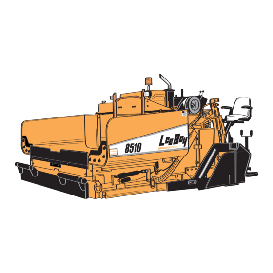
8510 CONVEYOR PAVER
Manual No. 986947
For Units with Serial No. 44987 and higher
Published 10-03-06
Advertisement
Table of Contents
Troubleshooting

Related Manuals for LeeBoy 8510


Summary of Contents for LeeBoy 8510
- Page 1 OPERATIONS, SERVICE AND PARTS MANUAL 8510 CONVEYOR PAVER Manual No. 986947 For Units with Serial No. 44987 and higher Published 10-03-06...
- Page 3 500 Lincoln County Parkway Ext. Lincolnton, NC 28092 Tel: 704-966-3358 Fax: 704-483-5802 www.LeeBoy.com USERS’ REFERENCE GUIDE DELIVERY DATE______________________________________ UNIT SERIAL NUMBER_________________________________ ENGINE TYPE________________________________________ ENGINE NUMBER_____________________________________ DEALER'S NAME AND ADDRESS _____________________________________________________ _____________________________________________________ PHONE NUMBER_______________________________________ EQUIPMENT HOURS____________________________________ SERVICE MANAGER ____________________________________ 8510 Conveyor Paver...
- Page 5 6. The warranty responsibility on all engines warranty. Remanufactured parts purchased rests with the respective manufacturer. by a LeeBoy dealer will carry a ninety (90) 7. LeeBoy may have support agreements with day warranty. some engine manufacturers for warranty and parts support.
- Page 7 This manual should be used with all related If any questions arise concerning this publication or supplemental books, engine and transmission others, contact your local LeeBoy Distributor for the manuals, and parts books. Related Service latest available information. Bulletins should be reviewed to provide information Contents of this manual are based on information regarding some of the recent changes.
- Page 8 8510 CONVEYOR PAVER 8510 Conveyor Paver...
- Page 9 RECEIVING THE 8510 CONVEYOR PAVER ........
- Page 10 8510 CONVEYOR PAVER TABLE OF CONTENTS (Continued) Page SCHEMATICS ..............4.31 TROUBLESHOOTING .
- Page 11 RECEIVING THE 8510 CONVEYOR PAVER ........
- Page 12 Legend Screed System. It is equipped with electric and manual thickness controls and an 8 ft to 15 ft (2.8 m to 4.5 m) wide screed. The 8510 Conveyor Paver is capable of placing bituminous base, binder and surface courses, such as lime or Portland cement, stabilized sub-base, and graded aggregate materials up to a thickness of 6 inches.
- Page 13 OPERATION Refer to OPERATION, Section 3 in this manual, for information needed to operate the 8510 Conveyor Paver safely. The operator of this equipment should READ, UNDERSTAND, and FOLLOW the operating instructions. Cautions are provided in the front of this manual and in the OPERATION section.
- Page 14 In addition, some machines use or contain hazardous chemicals which may require a specific Material Safety Data Sheet (MSDS). If such information is necessary for the safe operation of this machine, those MSDSs are included on the following pages. 8510 Conveyor Paver...
- Page 15 NOTE: It is the responsibility of the owner and operator to make sure that all decals are readable and located on the machine as designated by the manufacturer. FIGURE 1-1. DECALS and DECAL LOCATIONS 8510 Conveyor Paver...
- Page 16 CHECK that all safety decals and signs are in place and readable. These are as important as any other equipment on the machine. SAFETY STOP DANGER: Never work under the hopper without placing safety prop in position. See Figure 1-2. FIGURE 1-2. SAFETY PROP 8510 Conveyor Paver...
- Page 17 BE SURE the correct battery polarity is observed (negative (-) to negative (-) and positive (+) to positive (+), when connecting a battery charger or jumper cable. DO NOT tip batteries more than 45 degrees. Electrolyte solution is caustic and explosive. 8510 Conveyor Paver...
- Page 18 BE SURE the unit is stored in an area that is firm, level and free of debris. STORE the machine inside a building, or cover it with a weather-proof tarpaulin and support the wheels securely. Refer to MAINTENANCE, Section 4, for more detailed instructions. 8510 Conveyor Paver...
- Page 19 TABLE 2-7. TYPES OF LUBRICANTS..........2.4 8510 Conveyor Paver...
- Page 20 Section 2 SPECIFICATIONS GENERAL INFORMATION Tables 2-1 through 2-7 list the engine and system specifications for the 8510 Conveyor Paver. TABLE 2-1. ENGINE SPECIFICATIONS ITEM CHARACTERISTIC ENGINE Model and Manufacturer ....Hatz, 4L41C (Silent Pak) Type .
- Page 21 Basic Screed Width ....8 ft. (2.44 m) Maximum Screed Width ....15 ft. (4.57 m) 8510 Conveyor Paver...
- Page 22 Grease ......Shell Avania EP Grease or Equivalent Chain Lube ......Chain Lube 8510 Conveyor Paver...
- Page 23 GENERAL INFORMATION ............3.20 8510 Conveyor Paver...
- Page 24 TIE DOWN PROCEDURE ............3.29 8510 Conveyor Paver...
- Page 25 GENERAL INFORMATION OPERATING CONTROLS, INDICATORS, AND GAUGES This section provides the Operating instructions for the 8510 Conveyor Paver. Before starting or oper- WARNING: Do not start or operate the 8510 ating the machine, it is important to READ, Conveyor Paver before reading,...
- Page 26 Controls flow of propane to right screed burner. Steering and Speed Handles control the Control Module Speed and Steering Control (see Figure 3-3). Hydraulic Controls Contains the hydraulic controls that operate the Screed and other Functions (see Figure 3-4). 8510 Conveyor Paver...
- Page 27 Section 3 OPERATION FIGURE 3-2. MAIN DASH PANEL 8510 Conveyor Paver...
- Page 28 Left Conveyor 3-Position Selects automatic or manual Automatic/Manual automatic center override for left conveyor. return from MANUAL position Center is OFF position. For automatic operation set switch to AUTOMATIC position. MANUAL position provides override. 8510 Conveyor Paver...
- Page 29 (When in TRAVEL red 2-SPEED Light (Item 14) will illuminate.) IMPORTANT: High speed is only for traveling. Never pave in high speed. Rear Work Lights 2-Position toggle Used to turn the rear work lights switch ON or OFF. 8510 Conveyor Paver...
- Page 30 Light indicates if unit is charging. NOTE: If working properly, the light illuminates with the switch, and goes out when the engine cranks. If battery indicator light does not illuminate with key ON, the unit will not charge. 8510 Conveyor Paver...
- Page 31 Controls stopping the machine. Run/Stop 2-Position toggle switch When switch is set to STOP the machine stops (pauses). When switch is set to RUN the machine resumes its prior speed. Never use on a hill, use for flat ground only. 8510 Conveyor Paver...
- Page 32 Push the lever upwards to raise the conveyor (SEE WARNING). Pull the lever downward to lower the conveyor. WARNING: Always fold side wings on hopper out before raising conveyor. Place safety prop in place immediately. 3.10 8510 Conveyor Paver...
- Page 33 Side Wings Up/Down handle Used to move the side wings in or out. Push the lever upwards to move side wings in. (Never fold in with full hopper) Pull the lever downward to move side wings out. 8510 Conveyor Paver 3.11...
- Page 34 Pull the lever downward to turn the right auger on. Throttle Up/Down handle Used to set the engine RPM. Pull the lever out for higher RPM. Push the lever in for lower RPM. Turn to lock. FIGURE 3-5. PAVING CONTROLS 3.12 8510 Conveyor Paver...
- Page 35 Used to check oil level in hydraulic Point oil tank. Conveyor Drive Screws with jam nuts for adjusting Chain Adjustment the conveyor drive chain tension. Spray Down Hose Used to lubricate and keep asphalt from hardening on the machine. 3.13 8510 Conveyor Paver...
- Page 36 NOTE: Do not engage glow plugs for over 2 minutes at a time. 5. When engine starts and is running smooth, throttle back to idle by pushing in the throttle cable until idle speed is reached. 3.14 8510 Conveyor Paver...
- Page 37 (CW) to start position. FIGURE 3-8. SPEED AND STEERING 4. When engine starts and is running smooth, CONTROL MODULE throttle back to idle by pushing in the throttle cable until idle speed is reached. 8510 Conveyor Paver 3.15...
- Page 38 STOP position. When the machine is the travel speed. stopped with the toggle switch, the machine will resume travel at the last speed of travel when the switch is set to the RUN position. 3.16 8510 Conveyor Paver...
- Page 39 Heating should not only be performed at the beginning of the job, but also if the machine is idle for a long time between loads (allowing screed plate to cool). FIGURE 3-10. BURNER VALVES 8510 Conveyor Paver 3.17...
- Page 40 (Figure 3- for operating the feeder. 11, item 2). Turn ON valve (item 3) for extension burner and use lighter to light. Place burner back into holding socket and repeat this process for opposite side. 3.18 8510 Conveyor Paver...
- Page 41 Refer to the paragraph CONVEYOR FLIGHT CHAIN ADJUSTMENT in Section 4. NOTE: Check adjustments every 100 hours. CAUTION: Never work on conveyors with engine running. FIGURE 3-13. FLIGHT SCREWS AND SCREED HEIGHT GAUGES 8510 Conveyor Paver 3.19...
- Page 42 Cut-off gates are designed to break away from cylinders when hitting a manhole or other hard objects. This break away occurs only in forward gear, not in reverse. FIGURE 3-14. SPRAY DOWN HOSE AND WAND 3.20 8510 Conveyor Paver...
- Page 43 The sensors will turn the auger OFF and ON. NOTE: The sonic auger adjustment dial adjusts the amount of material needed. FIGURE 3-16. SONIC AUGER ADJUSTMENT FIGURE 3-15. AUGER EXTENSIONS 8510 Conveyor Paver 3.21...
- Page 44 3. Adjust height of material at endgate with the GENERAL INFORMATION sonic auger adjustment (see Figure 3-16). Turn The 8510 Conveyor Paver is equipped with the dial to keep the extension full. Be careful electric and manual thickness controls and an 8 ft not to over run the extension with the material.
- Page 45 WARNING: Before starting forward, make cer- tain that no one is in front of the Paver. WARNING: Avoid low hanging limbs, power lines, and other foreign objects that can endanger machine or crew. FIGURE 3-18. STARTER BLOCKS 8510 Conveyor Paver 3.23...
- Page 46 Leading edge crown aids material flow under crown setting (see Figures 3-20 and 3-21). the screed plate only. Trailing edge crown puts a crown in the mat. (NUT MUST BE LOOSE BEFORE ADJUSTING CROWN & VALLEY) FIGURE 3-20. MAXIMUM CROWN 3.24 8510 Conveyor Paver...
- Page 47 8. If making a cold joint, set endgate down about the weight of the screed. This will 1/4 inch (0.6 cm), this will give a nice even edge. cause screed compaction to vary. FIGURE 3-22. END GATES 8510 Conveyor Paver 3.25...
- Page 48 AUTO position and convey material back to screed. NOTE: Augers are not needed when paving a basic 8-foot pull. 6. Open cut-off gates under auger and start paving. Move slowly at first so adjustments can be made to screed. 3.26 8510 Conveyor Paver...
- Page 49 Paver - STOP - LOOK - THINK. ATTENTION:Make sure engine is operating at a high enough RPM so that the hydraulic pump is providing suffi- cient flow to operate all functions properly. FIGURE 3-23. UNLOADING 8510 Conveyor Paver 3.27...
- Page 50 NOTE: Always have a helper on the ground to 8. Shut down engine. assist the operator in moving the Paver onto the transport. 9. Secure Paver to transport as directed by regulations. FIGURE 3-24. CORRECT LOADING POSITION 3.28 8510 Conveyor Paver...
- Page 51 4. Make sure all chains are tight before moving. Paver at the D-rings (see Figure 3-26). 2. Attach tie down chains to the screed end of Paver at the D-rings (see Figure 3-26). FIGURE 3-26. TIE DOWN POINTS 8510 Conveyor Paver 3.29...
- Page 52 Section 3 OPERATION 3.30 8510 Conveyor Paver...
- Page 53 GENERAL INFORMATION ............4.17 8510 Conveyor Paver...
- Page 54 Installation ............. . . 4.27 8510 Conveyor Paver...
- Page 55 FAULT CODES FOR STATUS LED ..........4.55 8510 Conveyor Paver...
- Page 56 MAINTENANCE GENERAL INFORMATION ROUTINE MAINTENANCE This section gives the necessary procedures for routine and general maintenance on the 8510 GENERAL INFORMATION Conveyor Paver. Before starting any Maintenance Maintenance must be a planned program that program on the machine, it is important to READ,...
- Page 57 500 HOURS or SEMI-ANNUALLY Engine Fuel Filter (Main) Replace 310080 Engine Fuel Filter (In-Line) Replace 310090 Engine Coolant Replace 50/50 Antifreeze Hydraulic Oil Replace VG32 Hydraulic Filter (Charge) Replace 290030 Hydraulic Strainer Replace 36123 Torque Hubs Fill 50W Gear Lubricant 8510 Conveyor Paver...
- Page 58 Section 4 MAINTENANCE FIGURE 4-1. LUBRICATION POINTS 8510 Conveyor Paver...
- Page 59 Any part of the machine that comes in contact with the asphalt Daily LEGEND GREASE WITH SHELL AVANIA EP GREASE 2 OR EQUIVALENT SPRAY WITH RELEASE AGENT, CLEANING SOLVENT OR CHAIN LUBE FIGURE 4-2. EXTENSION SLIDE LUBRICATION FIGURE 4-3. SCREED LUBRICATION POINTS POINTS 8510 Conveyor Paver...
- Page 60 1990 1490 2380 1780 3230 2420 12 UNF 1670 1250 2270 1700 2710 2040 3680 2760 1-1/2 6 UNC 1950 1460 2640 1980 3160 2370 4290 3210 12 UNF 2190 1650 2970 2230 3560 2670 4820 3620 8510 Conveyor Paver...
- Page 61 428.04 321.03 580.0 435.0 M24 x 3 516.12 409.59 740.0 555.0 754.38 557.19 1010.0 755.0 M27 x 3 797.04 597.78 1080.0 810.0 1084.86 811.80 1470.0 1100.0 M30 x 3.5 1084.86 811.80 1470.0 1100.0 1476.00 1107.00 2000.0 1500.0 8510 Conveyor Paver...
- Page 62 WARNING: If maintenance must be performed with engine running, do not leave machine unattended. GENERAL INFORMATION Preventive maintenance on the 8510 Conveyor CHECKS AND ADJUSTMENTS Paver will provide years of trouble-free operation. Adjustments can be performed in the field with 1.
- Page 63 NOTE: Engine must be running to raise conveyor. 3. Raise conveyor by pushing the CONVEYOR RAISE/LOWER handle upward to the RAISE position and hold until conveyor is fully raised (see Figure 4-5). FIGURE 4-6. SAFETY PROP IN POSITION FIGURE 4-5. HOPPER RAISED 8510 Conveyor Paver 4.11...
- Page 64 Use the following procedure to make adjustment: setting may cause improper adjustment 1. Raise conveyors. Put keys in safe place. to track. 2. Secure safety prop (see Figure 4-6, item 1) to prevent conveyor from accidentally lowering. 4.12 8510 Conveyor Paver...
- Page 65 This indicates adjustment is close. NOTE: High gear adjustment is an Allen screw. 3. Finalize adjustment by making one quarter turns at a time until correct adjustment is made. FIGURE 4-8. CONVEYOR CHAIN ADJUSTING BOLTS 8510 Conveyor Paver 4.13...
- Page 66 On top of the housing is a small lever. Break the lead seal on the right side of the lever and turn the lever clockwise to lock in. The engine will now run until you unlock the override lever. 4.14 8510 Conveyor Paver...
- Page 67 NOTE: Relief pressure is set at 700 PSI at about three turns or until pressure release is track tension manifold (45). heard. 3. Make sure cartridge is tightened before moving machine. FIGURE 4-11. CONVEYOR MICRO-SWITCH LOCATION 8510 Conveyor Paver 4.15...
- Page 68 “B” slightly (Figure NOTE: Guide should be greased daily to 4-13, item 1) on the actuator arm (item 2). prevent wear. 5. Run extension out and grease guide with multi- purpose grease before working. 4.16 8510 Conveyor Paver...
- Page 69 6. Fill the engine with 12 qts (11.3 liters) of oil, using the correct engine lubrication oil. NOTE: For the correct type of lubrication oil see the engine manufacturer’s manual. FIGURE 4-14. HATZ ENGINE 7. Install the engine lubrication oil dipstick. 8510 Conveyor Paver 4.17...
- Page 70 NOTE: Tighten the filter element as directed on the filter element, by the filter WARNING: Stop the engine immediately if any manufacturer. fuel leakage is noted. Do not start the engine until the leakage problem is corrected. 4.18 8510 Conveyor Paver...
- Page 71 WARNING: Batteries contain sulfuric acid and damage to the machine’s electrical produce explosive gases which system. can cause serious injury. Do not allow flames or sparks to come near the battery. Do not smoke when servicing a battery. 8510 Conveyor Paver 4.19...
- Page 72 Keep the oil in the hydraulic oil reservoir at the reconnected properly. Use the following precautions correct level. An air space is designed into the to prevent damage to the alternator and/or hydraulic oil reservoir and allows for oil expansion, regulator: 4.20 8510 Conveyor Paver...
- Page 73 Add oil if needed. opening and secure in place with tape. 7. Install the hydraulic oil reservoir filler cap onto the reservoir filler neck and tighten securely. 8510 Conveyor Paver 4.21...
- Page 74 1″ out of chain. and secure the strainer with the three screws. NOTE: LeeBoy uses a 4 ft. (1.2 m) long x 11/16 in. 5. Fill the hydraulic oil reservoir with the correct, (2 cm) dia. rod with a 2 in. (5.08 cm) leg on...
- Page 75 8. Install the idler making sure the cylinder and the clip pin are in correct position. NOTE: LeeBoy uses a 4 ft (1.2 m) long x 11/16 in. (2 cm) dia. rod with a 2 in. (5.08 cm) leg on 9.
- Page 76 2.. Replace the track assembly back into the unit. 3. Install the hoses and clamps. 4. Reinstall the motor and torque the bolts to proper specs. 5. Lower unit and test. ATTENTION:Make sure hose connections are clean before removing and also before installing. 4.24 8510 Conveyor Paver...
- Page 77 3. Insert spline of torque hub into axle (7) and align the twelve mounting holes for the torque hub. 4. Attach the torque hub to the frame with the twelve 5/8″ bolts. 5. Torque bolts to 230 ft. lbs. (311 N•m). 8510 Conveyor Paver 4.25...
- Page 78 8. Remove C-188 master link (13) and lay the link out without installing a 1/2 link). chain away from the sprocket on the outer side. 9. The rear shaft (8) and outer C-188 sprocket (5) will pull straight out at this time. 4.26 8510 Conveyor Paver...
- Page 79 NOTE: Auger chains can be lubricated each 10. Check inner auger bearing (12) and replace at day by spraying oil or chain lube in this time if faulty. through slots where auger motor is adjusted. 8510 Conveyor Paver 4.27...
- Page 80 This will keep the screed relaxed. 7. Run extension out and grease the extension 7. Place the screed lids, the walkboards and the well before operating “in” and “out”. cylinder covers back on the screed. 4.28 8510 Conveyor Paver...
- Page 81 2. Carefully support auxiliary pump and align the mounting holes in the auxiliary pump with the mounting on pump. 3. Attach the pumps with the two mounting screws. 4. Torque the screws to 89 ft. lbs. (121 N•m). 8510 Conveyor Paver 4.29...
- Page 82 5. Operate Paver and check for leaks. NOTE: When installing motor dry, crank and let run for approximately 10 minutes to work air out of system before engaging to move. 4.30 8510 Conveyor Paver...
- Page 83 Section 4 MAINTENANCE SCHEMATICS 2 SPEED WIRING DIAGRAM FUSE BLOCK 8510 Conveyor Paver 4.31...
- Page 84 Section 4 MAINTENANCE LEFT CONVEYOR WIRING DIAGRAM RIGHT CONVEYOR WIRING DIAGRAM 4.32 8510 Conveyor Paver...
- Page 85 Section 4 MAINTENANCE SPECTRA GRADE CONTROL L/B DRIVE WIRING DIAGRAM SPECTRA GRADE CONTROL (with Slope add-on) ELECTRONIC STEERING WIRING DIAGRAM 8510 Conveyor Paver 4.33...
- Page 86 Section 4 MAINTENANCE SPECTRA GRADE CONTROL (with Slope add-on) L/B DRIVE WIRING DIAGRAM STANDARD GRADE CONTROL L/B DRIVE WIRING DIAGRAM 4.34 8510 Conveyor Paver...
- Page 87 Section 4 MAINTENANCE STANDARD GRADE CONTROL L/B DRIVE TOP-CON WIRING DIAGRAM 8510 GRADE CONTROL (STANDARD) L/B DRIVE 8510 Conveyor Paver 4.35...
- Page 88 Section 4 MAINTENANCE TSD AUGER WIRING DIAGRAM 8510 GRADE CONTROL WIRING WITH NEW AM MODULE TOPCON 4.36 8510 Conveyor Paver...
- Page 89 Section 4 MAINTENANCE HYDRAULIC SCHEMATIC (Sheet 1 of 2) 8510 Conveyor Paver 4.37...
- Page 90 Section 4 MAINTENANCE HYDRAULIC SCHEMATIC (Sheet 2 of 2) 4.38 8510 Conveyor Paver...
- Page 91 Section 4 MAINTENANCE MAIN DASH PANEL CONTROLS, INDICATORS, AND GAUGES (Sheet 1 of 2) 8510 Conveyor Paver 4.39...
- Page 92 Section 4 MAINTENANCE MAIN DASH PANEL CONTROLS, INDICATORS, AND GAUGES (Sheet 2 of 2) 4.40 8510 Conveyor Paver...
- Page 93 Engine cuts off and will not start. (Turns over but Blower belt broken Replace belt will not start) Faulty fuel solenoid Replace solenoid Faulty alternator Replace or rebuild Low Battery Idiot light, bad bulb Replace bulb 8510 Conveyor Paver 4.41...
- Page 94 700 PSI. Machine will not pull on Adjust Faulty hydraulic motor one or both sides Pump pressure should be 3700 PSI Pump pressure too low Rebuild or replace Faulty torque hub Replace axle Axle spline stripped 4.42 8510 Conveyor Paver...
- Page 95 Check ramps for easy access Flame coming out of end Raw gas from burners Adjust burners in or out of hole of screed Turn cutoff valve slowly to OFF, when flame goes out turn valve back on fully 8510 Conveyor Paver 4.43...
- Page 96 Loss of power to drives Relief out of adjustment Check pressure. Drive - 3700 PSI, feeder or augers feeders 2400 PSI, augers and cylinders 2000 PSI Replace Piston groups worn out Replace Auxiliary pump worn out 4.44 8510 Conveyor Paver...
- Page 97 Red LED (Status) System Status: 10 Hz blink rate No application loaded 0.5 Hz blink rate Application loaded and no error 0.5 Hz blink rate 4 bit blink code to describe fault Application loaded and error 8510 Conveyor Paver 4.45...
- Page 98 .._ _ Left Valve Reverse Coil Open or Short. Machine will revert to neutral causing the machine to stop. “.” = short flash = 0 “_” = long flash = 1 4.46 8510 Conveyor Paver...
- Page 99 Run the wire through a grommet when 3. Use #18 gauge wire or greater. #14 or #16 wire rounding a corner. is preferred. 7. Do not run wires near hot machine components. FIGURE 4-17. STEERING WIRING DIAGRAM 8510 Conveyor Paver 4.47...
- Page 100 Section 4 MAINTENANCE FIGURE 4-18. STEERING TROUBLESHOOTING GUIDE 4.48 8510 Conveyor Paver...
- Page 101 Section 4 MAINTENANCE FIGURE: 4-19 ENGINE WIRING DIAGRAM 8510 Conveyor Paver 4.49...
- Page 102 Turn the machine off. Open the dash board panel a. All the way Forward – loads the Sauer H1 and locate the Hi Output connector and plug it into parameters the Hi Output receptacle. b. All the way Reverse – loads the Rexroth parameters 4.50 8510 Conveyor Paver...
- Page 103 Run/Stop switch into the Run position. If two the Optimize/Calibrate connector from the control boxes are present place the other Run/Stop Optimize receptacle and turn off the power key. switch to the stop position. Turn machine on and the status light will blink 8510 Conveyor Paver 4.51...
- Page 104 6. Keeping power to the Plus One, unplug the 2. Move FNR Joystick to approximately 1/2 Optimize/Calibrate connector from the Calibrate joystick position, adjust the steering wheel as receptacle (this will write the calibration values necessary to make sure machine is traveling 4.52 8510 Conveyor Paver...
- Page 105 Run. adjusted with the Service Tool. Each joystick and steering wheel has been setup with individual profile and ramping to give smooth control. 8510 Conveyor Paver 4.53...
- Page 106 When the run signal is returned the output is immediately turned on and there is a .2 second delay on outputs to the pump coil. This delay allows time for the brake to release before the propel coils are energized. 4.54 8510 Conveyor Paver...
- Page 107 Left pump FWD or The output is open or short circuited REV output fault Check the coil and wires. Vibrator/ Electric Actuator relay The output is open or short circuited fault Check the relay and wires. 8510 Conveyor Paver 4.55...
- Page 108 Section 4 MAINTENANCE 4.56 8510 Conveyor Paver...
- Page 109 FIGURE 29. STRIKE OFFS & EXTENSIONS .........IPL.68 8510 Conveyor Paver...
- Page 110 ILLUSTRATED PARTS LIST FIGURE 1. SPROCKET DRIVE TRACK SYSTEM (AUTOMATIC HYDRAULIC ADJUSTABLE) 8510 Conveyor Paver IPL.2...
- Page 111 811328 LOCKWASHER; ROLLER 12MM 811330 CAP SCREW 811406 FRONT IDLER, TRACK (CASTED) 811329A YOKE, TRACK IDLER (SHORT) 851485 UNIVERSAL SEAL KIT, 3 1/2" HYD. CYL. 851644 BREATHER; CYLINDER 811331 HYD. CYL., TRACK TENSIONER 2404-10-8. ADAPTER,HYD. HOSE 8510 Conveyor Paver IPL.3...
- Page 112 ILLUSTRATED PARTS LIST THIS PAGE INTENTIONALLY LEFT BLANK 8510 Conveyor Paver IPL.4...
- Page 113 MANIFOLD, N/S TRACK TENSIONER HOSE ASSY. L.H. TRACK TENSIONER HOSE ASSY.R.H. TRACK TENSIONER 811365 SEAL, TORQUE HUB DRIVE SHAFT 851489A SEAL, HYD. MOTOR SNAP RING 930060 EXT. ROLLER W/BEARINGS 984379 R/H ROLLER MOUNT 984378 L/H ROLLER MOUNT 8510 Conveyor Paver IPL.5...
- Page 114 ILLUSTRATED PARTS LIST FIGURE 2. RUBBER TRACK UNDER CARRIAGE 8510 Conveyor Paver IPL.6...
- Page 115 YOKE, 8500 TRACK FRONT IDLER 983530 IDLER, FRONT B1 8515 982585 TRACK, RUBBER, CONTINUOUS 983166 TRACK, 135MM, POLYPADS, HEAVY DUTY 983588 TRACK ROLLER B-1 INNER FLANGE 986807 TORQUE HUB W/BRAKE (NEW IN 2006) 80278 CSHH, 625-18 X 1.25 8510 Conveyor Paver IPL.7...
- Page 116 ILLUSTRATED PARTS LIST VIEW - A VIEW - B VIEW - D FIGURE 3. CONVEYOR DRIVE ASSEMBLY 8510 Conveyor Paver IPL.8...
- Page 117 IDLER, CONVEYOR CHAIN FRONT 851123 TUBE ASSY. CONVEYOR FRONT CHAIN GUIDE 851653 CAPSCREW, 5/8”x2” FLAT SOCKET HEAD 851124 SHAFT, CONVEYOR FRONT IDLER 850162 ROLLER, CONVEYOR CHAIN GUIDE 851651 TUBE ASSY, CONVEYOR REAR DRIVE 851652 CAPSCREW, 5/8”x1” FLAT SOCKET HEAD 8510 Conveyor Paver IPL.9...
- Page 118 ILLUSTRATED PARTS LIST THIS PAGE INTENTIONALLY LEFT BLANK 8510 Conveyor Paver IPL.10...
- Page 119 FIGURE 3. CONVEYOR DRIVE ASSEMBLY CONT, UNITS NOMENCLATURE PART 123456 ASSY ITEM NUMBER. 410070 BUMPER, WATER TANK/CONVEYOR 851129 STOP RUBBER, (SCRAPER) 850170 SET SCREW 851116-1 PIPE W/BUSHING 851127L PAN, CONVEYOR BOTTOM, LH 851127R PAN, CONVEYOR BOTTOM, RH 8510 Conveyor Paver IPL.11...
- Page 120 ILLUSTRATED PARTS LIST & & & FIGURE 4. HOPPER COMPONENTS 8510 Conveyor Paver IPL.12...
- Page 121 BAR, 125 X 1.50 X 9.50 985581 FRONT LIP CLAMP 102-209-1A C5HH, .375-16 X 2.00GR5 102-407-1A CH5HH, .500- 13 X 1.50, GR5 851111 CSSH, .500- 13 X 2.00, GR5 102-607-1A CSHH, .625- 11 X 1.50, GR5 8510 Conveyor Paver IPL.13...
- Page 122 ILLUSTRATED PARTS LIST THIS PAGE INTENTIONALLY LEFT BLANK 8510 Conveyor Paver IPL.14...
- Page 123 FIGURE 4. HOPPER COMPONENTS CONT. UNITS NOMENCLATURE PART 123456 ASSY ITEM NUMBER. 118-7 WASHER, LOCK, .625 117-5 NUT, HEX, HEAVY, .625-11 118-5 WASHER, LOCK, .500 117-5 NUT, HEX, HEAVY, .625-11 119-3 WASHER, FLAT, SAE, .375 143-3 NUT, LOCK, .375-16 8510 Conveyor Paver IPL.15...
- Page 124 ILLUSTRATED PARTS LIST FIGURE 5. AUGER ASSEMBLY 8510 Conveyor Paver IPL.16...
- Page 125 CHAIN, ROLLER, 60H X 52 PITCH 860049 MASTER LINK, #60H (N/S) 985796 ASSEMBLY, 12” AUGER EXT. SHORT R/H 985795 ASSEMBLY, 12” AUGER EXT. SHORT L/H 140610 FITTING, LUBE STR. 1/4-28 851647 ENDCAP, AUGER SHAFT 851645-1 SET SCREW, AUGER END MOUNT 8510 Conveyor Paver IPL.17...
- Page 126 ILLUSTRATED PARTS LIST FIGURE 6. CONVEYOR DRIVE CUTOFF, SCREED LIFT CYLINDERS 8510 Conveyor Paver IPL.18...
- Page 127 CAP SCREW, 5/16"-18 x 3 1/2" 119-2 WASHER, 5/16" FLAT 118-2 WASHER, 5/16" LOCK 116-2 NUT, 5/16"-18 HEX 850001 MANIFOLD ASSEMBLY, AUGERS AND 2- SPEED 851237A COIL, WITH DIODE, 12 V SINGLE TERMINAL (AUGERS& 2 SPEED) 981699 PLATE, 8515 AUGER BACK 8510 Conveyor Paver IPL.19...
- Page 128 ILLUSTRATED PARTS LIST FIGURE 7. HYDRAULIC COMPONENTS L/H SIDE 8510 Conveyor Paver IPL.20...
- Page 129 COIL, 12V (H.P.S.) 851628-3 NUT, COIL RETAINER (H.P.S.) 850001 MANIFOLD, AUTO AUGER/ 2-SPEED (H.P.S.) 851235 CARTRIDGE VALVE, AUTO AUGER (H.P.S.) 851236 CARTRIDGE VALVE, 2-SPEED (H.P.S.) 850003 CARTRIDGE VALVE, 2-SPEED 851237A COIL, W/ DIODE,12V 851689 FLOW DIVIDER SCREED 8510 Conveyor Paver IPL.21...
- Page 130 ILLUSTRATED PARTS LIST 17 18 HOSE REEL MAIN VALVE BANK ITEM No.1 FIGURE 8. MAIN VALVE SPRAY DOWN 8510 Conveyor Paver IPL.22...
- Page 131 NOZZLE, FUEL WASH-DOWN HANDLE 920224 HOSE, TO SPRAYDOWN HANDLE 850101 TAB, AUGER LOCKOUT 851448 PRESSURE SWITCH (FLOWJET PUMP) SEAL KITS FOR VALVES 910059 SEAL KIT, VALVE SPOOL 910062 SEAL KIT, VALVE SECTION 910065 KIT, SEAL (RELIEF VALVE) 8510 Conveyor Paver IPL.23...
- Page 132 ILLUSTRATED PARTS LIST FIGURE 9. SPECIAL COMPONENTS L/H SIDE DASH 8510 Conveyor Paver IPL.24...
- Page 133 DASH, COMPLETE 8500/8000D 211748-02 STROBE LIGHT 160040A WORK LIGHT 920238 HANDLE & CHORD REMOTE 900080 SWITCH, REMOTE (ONLY) 900082 CORD, REMOTE 853962 ASSY. BEACON LIGHT POST 910-0260LD WIRING HARNESS MAIN L/D 910-0260HD WIRING HARNESS MAIN H/D 8510 Conveyor Paver IPL.25...
- Page 134 ILLUSTRATED PARTS LIST FIGURE 10. PUMP COMPONENTS SUNDSTRAND ELECTRONIC STEERING 8510 Conveyor Paver IPL.26...
- Page 135 HYD.PUMP, TANDEM PROPULSION (W/E.D.C.) (SUNSTRAND) 851525 Hydraulic PUMP TANDEM (REX ROTH) DEN CONNECTOR 985663 Hydraulic PUMP TANDEM (REX ROTH) 320235 O-RING (PIGGYBACK TO MAIN PUMP) (N/S) 986378 STEERING BOX W/DUAL JOYSTICKS (FIRST EDITION) (N/S) 986510 WIRE HARNESS (FIRST EDITION) (N/S) 8510 Conveyor Paver IPL.27...
- Page 136 ILLUSTRATED PARTS LIST FIGURE 11. H1 PUMP & CONTROLS 8510 Conveyor Paver IPL.28...
- Page 137 DUAL JOYSTICKS, ONTO BOX (+) ONE 851548 CURLY CORD, STEERING BOX TO JUNCTION BOX 987135 CONTROLLER, 50 DIN,. (+) ONE 987133 HARNESS (+) ONE TO PUMPS 36808 ‘O’ RING, PIGGYBACK TO MAIN 987132 KIT, DUAL JOY STICK CONTROL (+) ONE 8510 Conveyor Paver IPL.29...
- Page 138 ILLUSTRATED PARTS LIST FIGURE 12. ENGINE AND PUMP COMPONENTS FIGURE 12. ENGINE AND PUMP COMPONENTS 8510 Conveyor Paver IPL.30...
- Page 139 BELT, ALTERNATOR / BLOWER 320270 STARTER MOTOR 320280 SOLENOID, STARTER 320290 BLOWER FAN 320300 ALTERNATOR, 12 VOLT 310060 ELEMENT, AIR FILTER 320120 LEVER, ENGINE THROTTLE 320110 DIPSTICK, ENGINE OIL LEVEL 310080 ELEMENT, FUEL FILTER 310070 ELEMENT, OIL FILTER 8510 Conveyor Paver IPL.31...
- Page 140 ILLUSTRATED PARTS LIST THIS PAGE INTENTIONALLY LEFT BLANK 8510 Conveyor Paver IPL.32...
- Page 141 ILLUSTRATED PARTS LIST FIGURE 12. ENGINE AND PUMP COMPONENTS CONT. UNITS NOMENCLATURE PART 123456 ASSY ITEM NUMBER. 851567 SOLENOID, FUEL SHUT-OFF 853490 SENDING UNIT, OIL PRESSURE HAT001603700 GASKET, MUFFLER TO MANIFOLD 310090 IN-LINE FUEL FILTER 8510 Conveyor Paver IPL.33...
- Page 142 ILLUSTRATED PARTS LIST FIGURE 13. KUBOTA ENGINE 8510 Conveyor Paver IPL.34...
- Page 143 CAP, RADIATOR 986537-12 ALTERNATOR 171090 CLAMP, T BOLT 3” 37163 HUMP HOSE, REDUCER 3.50-3.00 ID 171109 CLAMP, T-BOLT 3.50 NOMINAL 23252 ACTUATOR, EMULSION/THROTTLE 980318 CONNECTOR, REAR, ELECTRIC SCREW 982157 LINKAGE, THROTTLE 980317 CONNECTOR, FRONT, ELECTRIC SCREW 8510 Conveyor Paver IPL.35...
- Page 144 ILLUSTRATED PARTS LIST VIEW IN DIRECTION OF ARROW ‘A’ CHARGE FILTER FIGURE 14. FILTER LOCATION & ACCESSORIES (HATZ) 8510 Conveyor Paver IPL.36...
- Page 145 LINKAGE 900076 SCREWS 900077 LOCK WASHER 900078 900079 PIN, COTTER (1/4) 310060 ELEMENT, AIR FILTER (HATZ DIESEL) 320500 COVER,ENGINE ACCESS(HATZ 4L41C 851163 SHIELD, HEAT 4 CYLINDER (HATZ) 310070 OIL FILTER, HATZ 900144 SENSOR, HUD. OIL TEMP. 8510 Conveyor Paver IPL.37...
- Page 146 ILLUSTRATED PARTS LIST FIGURE 15. R/H DRIVE & FUEL TANK 8510 Conveyor Paver IPL.38...
- Page 147 CABLE, 135” X 3” (R/H AUGER) 920136 CABLE, 135” X 3” (R/H EXT) 350080 PIN, CLEVIS 1/4" 960019 PIN, COTTER 920145 ROD FOR RIGHT HAND 5/8 119-7 LOCKWASHER, 5/8" 116-7-1 NUTS, JAM (5/8 920210 CASTED HANDLE, R.H. CONTROL 350050 CLEVIS, 1/4" 8510 Conveyor Paver IPL.39...
- Page 148 ILLUSTRATED PARTS LIST & 20 13 FIGURE 16. SEAT, WALKWAY & OTHER COMPONENTS 8510 Conveyor Paver IPL.40...
- Page 149 NUT, HEX 5/8" 102-615-1A CAPSCREW, 11 x 3 1/2" 920210A LEVER, SCREED EXT. REMOTE 350050 CLEVIS, 1/4" 350080 PIN, CLEVIS 910057 PIN, COTTER 920120 CABLE, 104” X 3” 160320 HORN, BACKUP ALARM 230062 BRACKET, W/CLAMP, LPG TANK MOUNT 8510 Conveyor Paver IPL.41...
- Page 150 ILLUSTRATED PARTS LIST FIGURE 17. SEAT WALKWAY & OTHER COMPONENTS 8510 Conveyor Paver IPL.42...
- Page 151 UNITS NOMENCLATURE PART 123456 ASSY ITEM NUMBER. 360010 SEAT ASSY W / ARMREST, WHITE 920024 SUPPORT, SEAT H/D 851168A WALKWAY, UPPER 851169 TOOL BOX 982965L ASSEMBLY, VIBRATOR L/H 982965R ASSEMBLY, VIBRATOR R/H 985777 CITRUS TANK ASSY. 8510 Conveyor Paver IPL.43...
- Page 152 ILLUSTRATED PARTS LIST FIGURE 18. EXPANDABLE SCREED ASSEMBLY (PART I) 8510 Conveyor Paver IPL.44...
- Page 153 WASHER, 5/8" FLAT 983405 MOTOR, HYDRAULIC SCREED VIBRATOR (8515) 870172 TURN BUCKLE, CROWN & VALLEY (FRONT) 870190 CHAIN, CROWN & VALLEY #40 870182 TURN BUCKLE, CROWN & VALLEY (REAR) 851195 HANDLE, CRANK 102-607-1A CAPSCREW, 5/8"x 1 1/2" 8510 Conveyor Paver IPL.45...
- Page 154 ILLUSTRATED PARTS LIST THIS PAGE INTENTIONALLY LEFT BLANK 8510 Conveyor Paver IPL.46...
- Page 155 GUIDE, EXTENSION TOP 102-406-1A CAPSCREW, 1/2"x 1 1/4" 118-5 WASHER, LOCK 1/2" 119-7 WASHER, FLAT, 1/2" 851196 PIN, SCREED EXTENSION HINGE 119-4 WASHER, FLAT, 7/16" 116-5 NUT, 7/16" 851600-1 BURNER PIPE EXTENSION 851197-1 BURNER PIPE, MAIN 8510 Conveyor Paver IPL.47...
- Page 156 ILLUSTRATED PARTS LIST FIGURE 19. EXPANDABLE SCREED ASSEMBLY (PART II) 8510 Conveyor Paver IPL.48...
- Page 157 R/H INSERT 856743L L/H INSERT 121-3 WASHER, WEDGE 851370 FLIGHT SCREW ASSEMBLY 870276 GRIP, HANDLE 851372 ROD GAUGE 870030 BEARING, SCREED FLIGHT SCREW 851373 LOCK, ARM * ITEMS NOT INCLUDED WITH PART. NO. 851370 FLIGHT SCREW ASSEMBLY 8510 Conveyor Paver IPL.49...
- Page 158 ILLUSTRATED PARTS LIST FIGURE 20. JOINTER ASSEMBLY 8510 Conveyor Paver IPL.50...
- Page 159 BRACKET, DEPTH SCREW CONTROL 890081 TILT SCREW, JOINTER ASSY. 982796 CABLE, POWER ULTRASONIC 982795 REMOTE POD, ULTRA SONIC 983050 COILED CORD 982794 SENSOR, ULTRA SONIC 982963 BAR, END GATE SKID 8515 987396 NUT, NYLON LOC 7/8-9 UNC-2B 8510 Conveyor Paver IPL.51...
- Page 160 ILLUSTRATED PARTS LIST FIGURE 21. SCREED ARM ASSEMBLY WITH CENTER TOE POINT 8510 Conveyor Paver IPL.52...
- Page 161 CAPSCREW, 3/8" -16 x 3/4" 119-3 WASHER, FENDER 3/8" 102-9-1A CAPSCREW, 1/4"x 2" 116-1 NUT, LOCK 1/4" 102-408-1A CAPSCREW, 1/2" -13 x 1 3/4" 115-5-A NUT, LOCK 1/2" 851221 BRACKET, GRADE CONTROL 851001A MOUNTING PLATE 6” ELECTRIC SCREW 8510 Conveyor Paver IPL.53...
- Page 162 ILLUSTRATED PARTS LIST FIGURE 22. PROPANE HEATER & AUTOMATIC IGNITORS 8510 Conveyor Paver IPL.54...
- Page 163 BURNER, WAND ASSY. ST5 IGNITER 851183 QUICK DISCONNECT, 1/4" MALE 982503 BURNER, EXTENSION ASSY. 982504 BURNER, WAND ASSY. ST5 IGNITER 230240 HOSE CLAMP 230024 IGNITER 230950 PIPE NIPPLE, 1/4” X 2” 230140 PIPE NIPPLE, 1/4” X CLOSE 8510 Conveyor Paver IPL.55...
- Page 164 ILLUSTRATED PARTS LIST 1&1A 2&2A FIGURE 23. AUGER EXTENSION 24” 8510 Conveyor Paver IPL.56...
- Page 165 SHIELD, AUGER EXTENSION (RIGHT) 851228 SHIELD, AUGER EXTENSION (LEFT) 851229 AUGER EXTENSION, (RIGHT) 851230 AUGER EXTENSION, (LEFT) 851231 SUPPORT, AUGER ADJUSTABLE 116-10 NUT, HEX 1" 854003 COUPLING HALF 854004 COUPLING HALF, (WELDMENT) 900404 DOUBLE ROW CHAIN ASSY. (50-2) 8510 Conveyor Paver IPL.57...
- Page 166 ILLUSTRATED PARTS LIST FIGURE 24. PAVER LEVELING CONTROL (TOPCON) 8510 Conveyor Paver IPL.58...
- Page 167 PIVOT MOUNT, TOPCON / SPECTRA PHYSICS 9090-1125 BRACKET, Z ARM 300060 HANDLE, BOLT 102-606-1A CAPSCREW, 5/8"-11x1 1/4" 119-7 WASHER, FLAT 5/8" 851421 SLOPE METER 851574 COILED CORD, TOPCON TRACKER / SLOPE 851584 SKI. 20’ 986609 COILED CORD REMOTE, TOPCON 8510 Conveyor Paver IPL.59...
- Page 168 ILLUSTRATED PARTS LIST JOG ON MACHINE FIGURE 25. SYSTEM 5 ( TOPCON) 8510 Conveyor Paver IPL.60...
- Page 169 PIVOT MOUNT, TOPCON/ SPECTRA 300060 HANDLE NUT, .625-11” 102-606-1A CSHH, .625-11X1.25 GR5 119-7 WASHER, FLAT, SAE, 625 851576 PIVOT MOUNT, (TOPCON/ SPECTRA) 119-7 WASHER, FLAT, SAE, .625 102-617-1A CSHH. .826-11 X 4.02 GR6 983414-09 ASSY. CB BRACKET 8510 Conveyor Paver IPL.61...
- Page 170 ILLUSTRATED PARTS LIST 11 RIGHT 11 LEFT FIGURE 26. PAVER GRADE CONTROLS SPECTRA PHYSICS 8510 Conveyor Paver IPL.62...
- Page 171 SHORT COILED CORD, R.H. REMOTE (FITS LBI-25) 851632 LONG COILED CORD, L.H. REMOTE (FITS LBI-25) 851265 CASE FOR SONIC TRACKER 851426 UNIVERSAL REMOTE 851630 COILED CORD, R-25 REMOTE 851687 BRACKET, REMOTE [SPECTRA] 851430 SLOPE MODULE, SCREED 851425 SHOCK MOUNT, SLOPE 8510 Conveyor Paver IPL.63...
- Page 172 ILLUSTRATED PARTS LIST FIGURE 27. TRUCK HITCH ASSEMBLY 8510 Conveyor Paver IPL.64...
- Page 173 PUSH ROLLER, TRUCK WHEEL 810110 BEARING, PUSH ROLLER (1 1/4") 930060 ROLLER EXTENSION, BUMPER 930065 PLATE, TRUCK HITCH COVER 930070 CYLINDER, 1.50 X 30.00 X 1.00 ROD 930075 SHAFT, ROLLER ASSEMBLY, TRUCK HITCH 851112 WASHER, COUNTER SUNK 8510 Conveyor Paver IPL.65...
- Page 174 Each bow may be raised individually until locked into open position. Each bow has two positions in which it can be locked open. This is to allow for arc stretch in canvas. •Part No. varies with color. FIGURE 28. UMBRELLA 8510 Conveyor Paver IPL.66...
- Page 175 ILLUSTRATED PARTS LIST FIGURE 28. UMBRELLA UNITS NOMENCLATURE PART 123456 ASSY ITEM NUMBER. 920235 UMBRELLA 8510 Conveyor Paver IPL.67...
- Page 176 ILLUSTRATED PARTS LIST STEP 1 STEP 2 1&2 INSTALLATION OF CUTOFF 3&4 5&6 FIGURE 29. STRIKE OFFS & EXTENSIONS 8510 Conveyor Paver IPL.68...
- Page 177 EXTENSION, 6' RIGHT SIDE 851635L ROLL UP CURB ATTACHMENT, 12"LEFT SIDE 851635R ROLL UP CURB ATTACHMENT, 12"RIGHT SIDE 851636L ROLL UP CURB ATTACHMENT, 24" LEFT SIDE (STANDARD 851636R ROLL UP CURB ATTACHMENT, 24" RIGHT SIDE (STANDARD) 8510 Conveyor Paver IPL.69...
- Page 178 ILLUSTRATED PARTS LIST NOTES 8510 Conveyor Paver IPL.70...
- Page 179 BAR, .375 X 6.25 X 7.00 IPL.13 853595 BAR, 125 X 1.50 X 9.50 IPL.13 851242 BAR, ADJUSTABLE SLIDE IPL.59 851118A BAR, CONVEYOR FLIGHT BAR (QUICK CHANGE) IPL.9 982963 BAR, END GATE SKID 8515 IPL.51 920041 BAR, GUIDE (OUTER) IPL.13 8510 Conveyor Paver IPL.71...
- Page 180 IPL.61 920120 CABLE, 104” X 3” IPL.41 920136 CABLE, 135” X 3” (R/H AUGER) IPL.39 920136 CABLE, 135” X 3” (R/H EXT) IPL.39 851520 CABLE, HEIGHT LOCATOR 3/16X90 WITH 5”STROKE IPL.53 982796 CABLE, POWER ULTRASONIC IPL.51 8510 Conveyor Paver IPL.72...
- Page 181 CH5HH, .500- 13 X 1.50, GR5 IPL.13 981688 CHAIN COVER, 8515 IPL.17 851121 CHAIN, CONVEYOR DRIVE IPL.9 851121 CHAIN, CONVEYOR DRIVE (#80) IPL.19 870190 CHAIN, CROWN & VALLEY #40 IPL.45 860090 CHAIN, ROLLER, 60H X 52 PITCH IPL.17 8510 Conveyor Paver IPL.73...
- Page 182 IPL.13 102-806-1A CSHH, .625-1” X .25 GR5 IPL.61 102-606-1A CSHH, .625-11 X 1.25, GR5 IPL.63 80278 CSHH, 625-18 X 1.25 IPL.7 102-617-1A CSHH. .826-11 X 4.02 GR6 IPL.61 851111 CSSH, .500- 13 X 2.00, GR5 IPL.13 8510 Conveyor Paver IPL.74...
- Page 183 IPL.31 985063 FLASHING, CENTER FRONT LIP IPL.13 985062 FLASHING, SIDE STRIP IPL.13 851370 FLIGHT SCREW ASSEMBLY IPL.49 910054FLS FLOAT, ASSEMBLY SCREED IPL.23 851689 FLOW DIVIDER SCREED IPL.21 320001 FOUR CYL. DIESEL ENG., HATZ 4L41C (SILENT-PAK) IPL.31 8510 Conveyor Paver IPL.75...
- Page 184 230038 HOSE, L.P.G. TEE TO SCREED EXTENSION IPL.55 920221 HOSE, PUMP TO HOSE REEL IPL.23 230034 HOSE, SCREED BURNER/IGNITER TO IPL.55 851225 HOSE, SCREED EXTENSION BURNER IPL.55 920224 HOSE, TO SPRAYDOWN HANDLE IPL.23 5120-1200 HOUR-METER IPL.25 8510 Conveyor Paver IPL.76...
- Page 185 KIT, SEAL (RELIEF VALVE) IPL.23 230010 L.P.G. TANK, 20 LBS. IPL.55 856743L L/H INSERT IPL.49 984378 L/H ROLLER MOUNT IPL.5 920210A LEVER IPL.39 320120 LEVER, ENGINE THROTTLE IPL.31 920210A LEVER, SCREED EXT. REMOTE IPL.41 320120 LEVER, THROTTLE IPL.37 8510 Conveyor Paver IPL.77...
- Page 186 NUT, 1/2"-13 HEX IPL.19 116-2 NUT, 5/16"-18 HEX IPL.19 116-7 NUT, 5/8" IPL.59 116-7-1 NUT, 5/8” IPL.3 116-5 NUT, 7/16" IPL.47 851628A-3 NUT, COIL(H.P.S.) IPL.21 811309 NUT, FOR PAD BOLT IPL.3 116-10 NUT, HEX 1" IPL.57 8510 Conveyor Paver IPL.78...
- Page 187 PIVOT MOUNT, (TOPCON/ SPECTRA) IPL.61 851575 PIVOT MOUNT, TOPCON / SPECTRA PHYSICS IPL.59 951575 PIVOT MOUNT, TOPCON/ SPECTRA IPL.61 981699 PLATE, 8515 AUGER BACK IPL.19 851152 PLATE, CUTOFF CYLINDER MOUNT IPL.19 HATO3878000 PLATE, MUFFLER BOTTOM IPL.31 8510 Conveyor Paver IPL.79...
- Page 188 SAFETY PROP, HOPPER IPL.13 851128 SCRAPER, CONVEYOR IPL.9 982797 SCREED BASE, NEW STYLE IPL.45 982797 SCREED, BASE (NEW STYLE) IPL.49 982971 SCREED, COMPLETE IPL.45 920070 SCREW WING, .375-6” X 1.00 IPL.61 851518 SCREW, ELECTRIC (6"INCH) IPL.53 8510 Conveyor Paver IPL.80...
- Page 189 SNAPRING IPL.45 230300 SOLENOID VALVE, 12 VOLT L.P.G. IPL.55 851567 SOLENOID, FUEL SHUT-OFF IPL.33 320280 SOLENOID, STARTER IPL.31 851422 SONIC TRACER IPL.63 851579 SONIC TRACKER IPL.59 851186 SPACER IPL.45 811310 SPACERS IPL.3 851245 SPRING, TENSION IPL.59 8510 Conveyor Paver IPL.81...
- Page 190 IPL.7 811360 TORQUE HUB, FINAL DRIVE (1000, 8000 & 8500 IPL.3 851101 TRACK ASSY. W/ CASTED SHOES IPL.3 851101P TRACK ASSY., W / POLY PADS IPL.3 811304 TRACK PAD, CASTED IPL.3 851104 TRACK PAD, POLY IPL.3 8510 Conveyor Paver IPL.82...
- Page 191 118-7 WASHER, 5/8" LOCK IPL.19 118-7 WASHER, 5/8" LOCK IPL.45 851112 WASHER, COUNTER SUNK IPL.65 851112 WASHER, COUNTER SUNK 1/2 IPL.9 860036 WASHER, FENDER (1/4 IPL.19 119-3 WASHER, FENDER 3/8" IPL.53 119-7 WASHER, FLAT 5/8" IPL.59 8510 Conveyor Paver IPL.83...
- Page 192 910-0260HD WIRING HARNESS MAIN H/D IPL.25 910-0260LD WIRING HARNESS MAIN L/D IPL.25 160040A WORK LIGHT IPL.25 811329A YOKE, 8500 TRACK FRONT IDLER IPL.7 811329A YOKE, TRACK IDLER (SHORT) IPL.3 851423 Z BRACKET ARM, 1 3/4" IPL.63 8510 Conveyor Paver IPL.84...
Need help?
Do you have a question about the 8510 and is the answer not in the manual?
Questions and answers