Advertisement
Quick Links
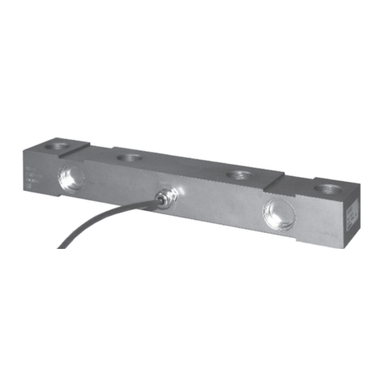
DSB7 7.5t & 15t Load Cell
Installation guidelines
For use onboard trucks and machines
Chassis-body mounted
on board weighing load cells
Trucks, Agricultural Machines
and Axle Weighbridges
7.5 Tonne (16500 Lbs) capacity
15 tonne (33000 Lbs) capacity
These guidelines provide guidance for the safe installation and operation of Flintec load cells.
Installations should be carried out by suitable qualified engineers.
Please read this manual carefully.
MSB Flintec
26 November 2014
Advertisement

Related Manuals for Flintec DSB7-7.5T


Summary of Contents for Flintec DSB7-7.5T
-
Page 1: Installation Guidelines
Axle Weighbridges 7.5 Tonne (16500 Lbs) capacity 15 tonne (33000 Lbs) capacity These guidelines provide guidance for the safe installation and operation of Flintec load cells. Installations should be carried out by suitable qualified engineers. Please read this manual carefully. -
Page 2: Table Of Contents
Contents Introduction & Weighing system overview Accuracy, Performance & Applications 3 - 4. Installation styles Cable orientation Preparation 6 - 10. Body - Chassis Alignment & Installation Welding procedure Torque values and fixing selection Installation examples, axle, side body-rail mount Technical specification and dimensions Cable, connectors and cable installation Routine maintenance & Installation check list MSB Flintec 26 November 2014... - Page 3 WARNING Failure to follow these instructions could cause a hazardous operating condition. Upon completion of the load cell installation, you or an appropriately trained service engineer will need to install a weighing indicator and calibrate the system; Calibration is simply an electronic adjustment of the scale to compensate for minute installation variations. Complete instructions for these procedures can be found in the weighing indicator's operator’s manual. Installation must be in accordance with national laws and regulations. An installation checklist has been provided in the back of this manual. Please refer to it during installation and check-off the important steps as they are completed. Weighing system overview Flintec on board weighing systems are ideal for industrial weighing applications and suitable for measuring either gross vehicle weight or the net weight of cargo being loaded or delivered. The basic system consists of load-supporting transducers (load cells) and an electronic meter (weighing indicator or display) capable of being calibrated to display the weight in convenient lbs or kgs, electrical cabling connecting the load cells and indicator: see diagram below. Typical four cell FRONT OFFSIDE Load cell REAR OFFSIDE Load cell arrangem Weighing Indicator or CPU vehicle management system Junction Box Input Channel 1 Analogue Load Cells 4, 6 0r 8 Ports Available Power Input Typically 9 - 30 Volts Dc From Ignition System FRONT NEARSIDE Load cell REAR OFFSIDE Load cell Truck body Typically 4, 6 or 8 DSB7 cells are ftted to 3.5-50 tonnes gross weight vehicles. MSB Flintec 26 November 2014...
- Page 4 Chassis Tipping Trailer Tipping Trailer Front end tipping arrangement Under-body tipping arrangement Load cell Load cell Load cell Load cell 4 Axle Rigid Tipping Body 2/3 Axle Rigid Tipping Body Load cell Load cell Load cell Load cell Chassis Chassis Agricultural machines Agricultural machines Load cell Load cell Load cell Load cell MSB Flintec 26 November 2014...
-
Page 5: Installation Styles
In-line mounted load cell An in-line mounted load cell is installed between the flanges of the upper body-rail and lower chassis frame and aligned with those frame members. Load spreading plates, sometimes called cover plates, fish-plates or angle sections are frequently used to spread the load over a greater area. A chassis or body subframe may be required where the body is prone to flexing. Frame stiffener (gusset or rib) Mounting angles (provides additional Body superstructure strength) frame member Chassis superstructure frame member Out-board mounted load cell An out-board mounted load cell is installed alongside the frame members using brackets located out-board of the chassis and body frame rails. Shown here are both bolted and welded methods of attachment the top & bottom load cell brackets. Spreader/cover plate Top welded Top bolted mounting bracket mounting bracket Body superstructure frame member Chassis superstructure Bottom welded-on frame member mounting bracket Bottom bolted-on mounting bracket MSB Flintec 26 November 2014... -
Page 6: Cable Orientation
Allows for either inboard or outboard facing cable connectors Outboard facing cable connector is usually required The most common position for load cell mounting is to position the load cell so that the spacer blocks are underneath the load cell. However, installation can sometimes be simplified by inverting the load cell and installing with the bearing plates above the load cell, especially when combined with the outboard mounting style. An air gap is recommended to prevent the build-up of debris beneath the load cell. Minimum air gap: 7.5 t = 6 mm (1/4") 15 t = 10.00 mm (3/8") Don't allow bolts to protrude here Typical bolted-on installation. An all-welded installation is also possible - both attachment methods are application specific. Cable Orientation The load cell can be orientated so that the cable connector is located on either the outboard or inboard side of the load cell. Outboard located cable exit is generally more accessible for installation and service, but may need a cover plate for protection from road damage. Inboard facing cable exit provides improved protection for the cable. Outboard mounted load cells generally have limited access for inboard facing cable exit. For this reason, inboard facing cabling is usually used only with in-line mounted load cells. Connector protection; Flintec recommends that a protective cover be provided to protect outboard facing connectors from road damage such as flying stones. Out-board facing In-board facing cable gland cable gland Typical installations. MSB Flintec 26 November 2014... -
Page 7: Preparation
Preparation Load cell mounting brackets are attached to the superstructure by means of welding or bolting. In order to provide for the mounting of load cells and mounting brackets (illustrated in later sections), some modification to the superstructure may be required. The modifications may be as simple as providing a flat surface for bracket welding or may be as extensive as providing a recess in the under frame for the mounting of the load cells. Modification to the superstructure will vary according to the specific type of installation to be performed; whether it is for a trailer suspension subframe assembly or for truck frame mounted systems supporting entire payload carrying superstructures. Outboard mounted load cells may only need space to weld or bolt load cell mounting brackets, while an in- line mounted load cell system will need holes drilled in the under frame of the superstructure for the load cell mounting bolts. Whenever making modifications to a structure, care must be taken to provide for bolt strength and rigidity (stiffness) for the finished installation. Every structure will deform (bend, twist or sag) to a certain degree when carrying a load. The installer must ensure that the modified structure is strong enough to prevent not only permanent (elastic) bending so that upper structural elements will not contact lower elements and create an alternative load path around the load cells. Excessive frame bending can be prevented by either adding a ‘glove’ (a structural supporting sleeve) to the frame, or by adding additional load cells in that area for more support. Frame Stiffeners: If the frame section above the load cell is an open section, such as a channel or ‘I’ beam, web stiffeners are required to avoid frame twist (see illustration below). The stiffeners are located near the ends of each bearing plate for inverted load cell mounting, or between the mounting holes for load cells installed with the bearing plates beneath the load cells. Recess Mounting: Often the most practical method for installing on-board frame mounted scales (particularly with an in-line mounted system) without an undesirable height increase of the trailer or body, is to provide a recess in the superstructure under frame. A general recommendation for this approach is shown in the following illustration. The installer should assure that any modified structure will retain the strength and stiffness properties of the original structure. Frame stiffeners Cover plate or glove (ribs or gussets) 10 mm (3/8") thick 10 mm (3/8") thick Flange 20 mm (0.75") thick Don't allow bolts to protrude here MSB Flintec 26 November 2014... -
Page 8: Body - Chassis Alignment & Installation
Flintec load cells are designed to be installed between the body and chassis of industrial trucks. It is imperative the load cells are installed in-line with the chassis and body rails with no misalignment or twisting forces projected on to the bolts or fixings. Alignment: Because the installation of load cells involves the separation of the body superstructure from the supporting chassis frame, care must be taken to ensure the separated elements are installed and in alignment; new build or retrofits. The body must sit flat and load cell mounting bolt-holes align without the use of additional tools. e.g. jemmy bars or jacks. Bolts should be inserted by hand and screwed by hand prior to final tightening with a torque wrench. Marking the relative positions on the frame elements before assembly is an effective means of assuring proper alignment. Also ensure the straightness of frame elements when cutting or welding to prevent undesirable bending or warping during assembly. The use of a simple frame stiffener (rib, gusset or stiff-back), welded into place prior to modification, is effective for this purpose. Mounting Structure: Optimum performance of DSB7 is dependent upon a solid mounting base for the load cells. Steel brackets of heavy construction are required. Since this is a thicker section than usually found on trucks, a cover plate may be necessary to evenly distribute forces to avoid stress concentrations and possible cracking in the thinner sections of the superstructure. Locating load cells in the immediate vicinity of cross members or other frame strengthening/stiffening elements to provide maximum support is also important for providing a structurally sound installation, as well as a reliable on-board weighing system. When separating and/or aligning the body to the supporting chassis frame, be careful when re-routing hoses, airlines, fuel lines etc. Some of these items may need to be replaced by longer ones to prevent secondary load paths which cause poor weighing performance. These items are also susceptible to damage if they are not of sufficient length to allow for frame separation or are not properly protected at installation. Upon completion of the installation, look closely at all the elements of the mechanical installation to avoid problems with pinched wires, ruptured hoses, etc., especially during the first operation of any moving structure such as a dump body. Body rail Spreader plate Pocket weld Top mounting bracket Bracket welded to chassis example MSB Flintec 26 November 2014... - Page 9 DSB7 15t DSB7 15t Bottom brackets (16500 Lbs) (16500) (33000) (33000) M12-1.75 1/2" (0.5") M16-2 1/2" (0.5") 5,000 kg 11000 Lbs 5,000 kg 11000 Lbs 7,500 kg 16500 Lbs 10,000 kg 22000 Lbs 7,500 kg 16500 Lbs 15,000 kg 33000 Lbs 15,000 kg 33000 Lbs For in-line installations, use the bolting recommendations for highway use regardless of road condition. Frame Rail Inspection: Inspect the frame rails to ensure they are clean, straight and free of cracks, corrosion, pitting, burrs or any other imperfections that may affect the installation and fit of the mounting angles/brackets, or the strength of the frame. Mounting Bracket/Angle Installation: Set the mounting angles (for in-line installations) or mounting brackets (for outboard installations) in place on the frame rails. Determine if and where they must be cut or contoured to allow clearance for existing bolts, rivets, spring hangers, etc., on the frame. Mark these locations on the mounting angles/brackets, allowing for a minimum 25 mm (1") radius -no sharp corners. Remove angles/brackets, trim as required, and grind edges smooth. NOTE: It is not necessary to cut out load cell mounting angles and brackets for easily removed items such as fuel tanks, battery boxes, etc. These items are simply repositioned or spaced out to conform to the added thickness of the load cell mounting angles/brackets. MSB Flintec 26 November 2014...
- Page 10 In-line installation Chassis frame (rail) Out-board installation Chassis frame (rail) Frame mounting bolts Clamp the mounting angles/brackets tightly to the frame. Be sure that the clearances and cut-outs are correct. Locate and drill holes per the recommendations in the chart on the previous page and bracket drawings in the fixing section on page 12 of this manual. NOTE: Bolt holes in mounting structures must be drilled, not burned. Holes should not be oversized more than 1 mm to ensure a snug fit for bolts. Use a minimum of bolts accordnig to the guide on previous page per mounting angle or bracket. Also locate bolts within 25 mm to 38 mm of each end of the mounting angle/bracket. Do the same for the edge of each cut out deeper than 25 mm. Attach the mounting angle/bracket using BS/ ISO/DIN Grade 10.9 (SAE Grade 8) quality bolts, Grade C lock nuts and a hardened washer under each lock nut. The bolts must have a diameter of M16 (5/8”) minimum for 15t cells and M12 (3/8") for 7.5t cells and sufficient length to provide a minimum of 3 threads past the end of the lock nut. Tighten all bolts to the proper torque value listed in the table on page 12. When welding brackets to non-heat treated frames, use a low hydrogen process and AWS E7018 rod or equivalent. Check the lengths of all connections for items that have been moved during the installation of the mounting angles/brackets. These connections may include battery cables, fuel lines, air lines, and electrical cables. MSB Flintec 26 November 2014...
- Page 11 Assemble upper mounting brackets to the load cells using the fixing kits where provided, (for in-line mounted systems where the load cells bolt directly to the upper frame structure, simply mount the load cell assemblies to the upper frame). Make sure the fixings are the proper length and do not bottom out in the tapped holes. If the mounting bolts are too long, damage to the load cells is possible. A dangerous operating condition could exist if the bolts are not secure. Top mounting bolts Upper mounting bracket (out board mount) Spacer blocks (see page 14 for dimensions - square plate is sufficient) The load cell/upper mounting bracket assemblies are now ready to be installed on the superstructure. To do this, place temporary spacers usually 20 mm to 25 mm (3/4" - 1") on the vehicle frame to provide the proper spacing between the superstructure and the vehicle frame. Lower the superstructure onto these spacers. Be sure to check the superstructure for proper alignment with the vehicle frame. Load cell upper mounting bracket assembly - (welded or bolted) Temporary spacer block Weld assembly to body frame along three sides & plug weld through holes Place the load cell assemblies on the vehicle frame mounting brackets which were installed in ‘Frame Preparation’. Adjust the load cell assemblies into their final position, verifying fit and clearances with the superstructure. Bolt or weld upper mounting bracket securely to the superstructure using a low hydrogen process and AWS E7018 rod or equivalent (DO NOT WELD BEARING PLATES YET). See ‘CAUTION’ on page 10 before proceeding with welding. Lift the superstructure and remove the temporary spacers. MSB Flintec 26 November 2014...
- Page 12 Weld load cell brackets in place (see caution below, and welding procedure on page 11 before proceeding with welding) Top bolted mounting bracket Body superstructure frame rail Bottom welded-on mounting bracket Chassis frame rail frame member Bracket welded to chassis example Caution: Bearing Plate Welding: Please read the welding procedures on the following two pages completely before proceeding. The welding of the bearing plates is the most crucial step in the installation process. Take precautions to ensure that the vehicle electrical system is not damaged by the welding. To prevent electrical current flow through the load cell, attach ground strap directly to the structure on the same side of the load cell on which welding is being done. Complete the attachment of the superstructure/load cell assembly in the following order (in accordance with the welding procedures on page 11): 1. Tack weld the bearing plates to the mounting angles or brackets. 2. Remove the slag from tacks and ‘feather’ end of tack with a grinder to provide a smooth transition for the root to pass as it passes through the tack. Welding can be completed without disassembly of load cells from bearing plates. Direct electrode away from unprotected underside of load cell. 3. Alternate welds from side-to-side and end-to-end to avoid weld distortion. MSB Flintec 26 November 2014...
-
Page 13: Welding Procedure
CAUTION: Take precautions to ensure that the vehicle electrical system is not damaged by the welding. Attach ground strap directly to vehicle frame member (not load cell body) to which the bearing plates are being welded to prevent electrical flow through load cell. Welding Process: Use a low hydrogen process and AWS E7018 rod or equivalent. The bearing plate may be welded using SMAW stick, GMAW spray transfer, or FCAW. The user should not use GMAW short circuit transfer. Weld Configuration: The bracket plates shall be attached using a single or multipass fillet weld sequence Deposited Weld Metal Fillet Sizes: The finish multipass fillet assembly shall be a minimum of 8 mm (1/3”). Preheat: The bearing plate and the base metal mounting surface shall be warmed in preparation for welding to reduce shrinkage stress. Any suitable torch arrangement is satisfactory. Spot heating shall be avoided. The preheat temperature shall be a MINIMUM of 20°C (68°F) and a MAXIMUM of 65° C (150°F). Cleaning Before Welding: Bracket components and bearing plates shall be visually inspected to verify that there is no oil, grease, dirt, paint or other foreign substance that will reduce the weld quality. Wehere brackets are welded to the body and/or chassis, mounting surfaces should be prepared using and angle grinder or power wire brush to remove all paint, primer, or other surface coating. An area the size of the bearing plate plus 25 mm (1") should be cleaned and ground to bare base metal. In process Cleaning: Each fillet shall be visually inspected with all slag cover removed, before proceeding with the next bead. A stiff wire brush or needle scaler may be used for slag removal. Final Inspection: Long service life depends on quality application of the fillet welds and THE FINAL SIZE OF THE FILLET. There shall be no undercut on either the upper leg (on the bearing plate) or the lower leg (frame base metal). Any undercut shall be repaired with an additional fillet or contoured by grinding to remove the mechanical notch. Visually inspect all weld stops and starts. Weld craters should be filled. All weld stops shall be staggered. A light coat of primer and paint may be applied after final inspection. Periodic Inspection: These primary load carrying fillet welds should be inspected during routine maintenance. WARNING: HEAT FROM WELDING MAY LOOSEN BOLTS. THEREFORE, ALL TORQUE VALUES SHOULD BE RECHECKED AFTER INSTALLATION WHEN ALL WELDS HAVE COOLED. MSB Flintec 26 November 2014... -
Page 14: Torque Values And Fixing Selection
Hexagon Head Screw Straight shank- part thread from end to bolt head. Full thread from end to bolt head. Use wasehers. Use wasehers. Strongest fixing. Suitable for the end and top fixings. Suitable for the end and top fixings. Suitable for frame mount fixings. Suitable for frame mount fixings. Socket Head Cap Screw Flat Countersunk Socket Cap Screw Full thread from end to bolt head. Full thread from end to bolt head. Suitable for the end and top fixings. Suitable for the end and top fixings where loads are low to Washers not normally needed. moderate such as a weigh platform. Allows the head to be recessed into the bracketry. Washers not normally needed. Suitable for frame mount fixings where cosmetics and available space is tight. Ideal where a top plate need to be flush fitting Example fixing styles The fixings into the DSB7 load cell are metric only: M16-1.5 (fine) and M24-2 (fine) metric fixings to ISO/DIN 961 are widely available in various lengths, check with the Flintec sales teams for availability of stocked fixings. MSB Flintec 26 November 2014... - Page 15 Load cell inverted Load cell inverted In-line Outboard No spacers Welded to body Welded to body Load cell inverted Load cell inverted Load cell on axle beam Plug welded upper body brackets Plug welded upper body brackets MSB Flintec 26 November 2014...
- Page 16 Protection according EN 60 529 Cable jacket PVC 4 core unshielded cable (AWG 24) 1.42" 1.90" Cable length 5 m, longer or shorter on request 1.65" 2.13" Connector M12 4-pin 0.24" 0.32" Cable diameter 5.5 mm (0.22") 0.5" 0.55" MSB Flintec 26 November 2014...
-
Page 17: Cable, Connectors And Cable Installation
Junction boxes MALE Wirable with cable gland Rewirable 4-pin M12 Connectors (also known as field attachments) Junction (splitter) boxes are internally wired in parallel for analogue systems and serial for CAN Open systems. 4, 6 and 8 way junction boxes have FEMALE signal sockets & MALE indicator cable sockets. Extender cables & Junction box to indicator cabeles On board weighing load cells and extensometers have 5 meter cable complete with moulded 4-pin M12 MALE cable as standard. Male-Female extender cables for longer reach applications are available in 1, 2, 3, 5, 7.5 & 10 metre lengths. A 2 into 1 ‘Y’ cable is availabe where two load cell are deployed. Cable Installation Flintec cables are specially designed to provide maximum signal strength and high reliability. Substitution of cabling other than Flintec supplied cabling may cause inconsistent and erratic readings. Care should be taken when routing cable to provide protection from sharp edges, driveline rotation, exhaust pipe, or any other potential damage. Secure in place with cable ties to a snug fit. Assembly of the cable connector to the junction box and indicator should not be forced. Align the 'keyways' and insert the cable connector. As the cable connector is being inserted, rotate the threaded sleeve clockwise until hand tight. Ensure the connector has been fully inserted for maximum moisture protection by wriggling the connector and re tightening the sleeve. MSB Flintec 26 November 2014... - Page 18 Routine Maintenance To ensure your onboard weigher operates safely and accurately follow these four periodic steps:- 1. Inspect all weld for signs of cracking or corrosion 2. Retighten all fasteners to specified torque values 3. Inspect cable and connectors for damage, tightness and cleanliness 4. Clean truck/trailer suzi connectors Flintec Group AB W4/5 Capital Point, Capital Business Park Wentloog Avenue, Cardiff, CF3 2PW - UK Tel +44 (0) 29 2079 7959 Fax +44 (0) 29 2079 7939 www.flintec.com MSB Flintec...
Need help?
Do you have a question about the DSB7-7.5T and is the answer not in the manual?
Questions and answers