Table of Contents
Advertisement
Quick Links
Advertisement
Table of Contents

Related Manuals for PCB Piezotronics EX619A11


Summary of Contents for PCB Piezotronics EX619A11
- Page 1 Model EX619A11 Charge Output Accelerometer Installation and Operating Manual For assistance with the operation of this product, contact PCB Piezotronics, Inc. Toll-free: 800-828-8840 24-hour SensorLine: 716-684-0001 Fax: 716-684-0987 E-mail: info@pcb.com Web: www.pcb.com...
- Page 2 Piezotronics, user servicing or repair is critical test. not recommended and, if attempted, may void the factory warranty. Routine PCB Piezotronics maintains an ISO- maintenance, such as the cleaning of 9001 certified metrology laboratory and electrical connectors, housings, and offers calibration services, which are...
- Page 3 E-mail: info@pcb.com representative. Warranty – All equipment and repair services provided by PCB Piezotronics, Inc. are covered by a limited warranty against defective material workmanship for a period of one year from date of original purchase. Contact...
- Page 4 PCB工业监视和测量设备 - 中国RoHS2公布表 PCB Industrial Monitoring and Measuring Equipment - China RoHS 2 Disclosure Table 有害物质 汞 镉 六价铬 (Cr(VI)) 多溴联苯 (PBB) 多溴二苯醚 (PBDE) 部件名称 铅 (Pb) (Hg) (Cd) 住房 PCB板 电气连接器 压电晶体 环氧 铁氟龙 电子 厚膜基板 电线 电缆 塑料 焊接...
- Page 5 Component Name Hazardous Substances Lead Mercury Cadmium Chromium VI Polybrominated Polybrominated (Pb) (Hg) (Cd) Compounds Biphenyls Diphenyl (Cr(VI)) (PBB) Ethers (PBDE) Housing PCB Board Electrical Connectors Piezoelectric Crystals Epoxy Teflon Electronics Thick Film Substrate Wires Cables Plastic Solder Copper Alloy/Brass This table is prepared in accordance with the provisions of SJ/T 11364.
-
Page 6: Operating Guide
General OPERATING GUIDE for use with PIEZOELECTRIC CHARGE MODE ACCELEROMETERS SPECIFICATION SHEET, INSTALLATION DRAWING AND CALIBRATION INFORMATION ENCLOSED PCB ASSUMES NO RESPONSIBILITY FOR DAMAGE CAUSED TO THIS PRODUCT AS A RESULT OF PROCEDURES THAT ARE INCONSISTENT WITH THIS OPERATING GUIDE. DOC: 55308 REV: NR ECO:41036... -
Page 7: Table Of Contents
TABLE OF CONTENTS OPERATING GUIDE ................................1 PIEZOELECTRIC CHARGE MODE ACCELEROMETERS ..................... 1 Cables in Explosive Atmospheres ........................... 3 High Temperature Differential Charge Output Sensor .................... 3 CABLING ..................................3 General Precautions and Considerations ......................... 3 2.1.1 Proper Cable Type and Care .......................... 3 Softline Cable ................................ -
Page 8: Cables In Explosive Atmospheres
INTRODUCTION Congratulations on the purchase of a quality PCB charge mode accelerometer. In order to ensure the highest level of performance for this product, it is imperative that you properly familiarize yourself with the correct mounting and installation techniques before attempting to operate this device. If, after reading this manual, you have any additional questions concerning this sensor or its application, feel free to call an Application Engineer at 716-684-0001 or the closest PCB representative. -
Page 9: Softline Cable
2.2 Softline Cable Special high temperature low-noise, shielded cable 2-wire cable assembly is required with charge mode sensors for applications up to 500°F to connect the transducer to the charge amp. When additional mechanical protection is required a stainless steel armor can be used. The shield acts as a Faraday cage to reduce electrical noise from corrupting the signals, and minimizes capacitively coupled noise from other electrical sources. -
Page 10: Installation Overview
3 INSTALLATION OVERVIEW Equipment Inspection Before installing the accelerometer, verify the insulation resistance (I/R) of the sensor is per specification. I/R can be out of specification due to mishandling and/or damage. 3.2 Polarity Test Use this test to verify the proper polarity response. Improper polarity will adversely affect the use of the sensor for machinery diagnostics such as balancing. -
Page 11: Route Mineral Insulated Hardline Cable
Step 2: Prepare a smooth, flat mounting surface on the machine casing. Then drill and tap a mounting hole in the center or on the corresponding bolt circle of the sensor as shown in Figure 2 and in accordance with the Installation Drawing for the specific sensor that is being mounted. -
Page 12: Bend Radius
cables along floors or walkways where they may be stepped on or become damaged or contaminated. Avoid twisting, kinking, or straining the cable. Shielded cables should have the shield grounded at one end only. 3.5.2 Bend Radius The minimum bend radius (r) for both soft-line and hardline cable is determined by the cable diameter as shown below: Bends Allowed... -
Page 13: Powering
4 POWERING 4.1 Installation Before connecting the low-noise cable from the accelerometer to the charge amplifier, be sure to ground both the charge amplifier and the cable. This ensures that an excessive static charge that may have accumulated across the accelerometer or cable is harmlessly discharged. Failure to observe this precaution can result in the destruction of the input FET of certain amplifiers. -
Page 14: High-Temperature Operation
5 HIGH-TEMPERATURE OPERATION Introduction When subjected to elevated temperature, all piezoelectric sensors/hardline cable systems exhibit decreased insulation resistance, due in part to the piezoelectric element, but due mostly to the hardline cable necessary to withstand the high temperatures. This situation can cause serious voltage offset problems in direct-coupled charge amplifiers. To solve this problem, the user must AC couple (capacitor) the charge amplifier to the sensor/cable system. -
Page 15: Solution To Reduced Resistance
increases, such that the output voltage can, with large ratios of R , become large enough to result in a large , perhaps large enough to be outside the normal output voltage range of the charge amplifier. Because of the feedback capacitor C , this output voltage change usually does not occur rapidly but rather, it manifests itself as a slow drift in the output voltage level. - Page 16 In a normal charge amplifier, the low-frequency response is set by the RC time constant, as established by the product of C and R . The system acts like a high-pass first order RC filter with a -3 dB frequency established by the relationship: Equation 2 f ...
-
Page 17: Other Precautions
5.5 Other Precautions Always remember to keep the OPR-GND switch on the charge amplifier in the GND position while connecting or disconnecting sensors, cable, or capacitor to the input connector. Stray or accumulated electrostatic charges may build to the point that they may saturate or even damage the input circuitry of the charge amplifier. -
Page 18: Back-To-Back Calibration Theory
to incorrect readings and costly errors. Therefore, in an effort to prevent the common mistakes associated with customer-performed calibration, this document includes a broad overview of the Back-to-Back Calibration technique. This technique provides a quick and easy method for determining the sensitivity of a test accelerometer over a wide frequency range. -
Page 19: Pcb Calibration Procedure
Figure 3. Typical Test Accelerometer Response 6.1.3 PCB CALIBRATION PROCEDURE Numerous precautions are taken at PCB to insure accurate and repeatable results. This section provides a brief overview of the primary areas of concern. Since the Back-to-Back Calibration technique relies on each sensor experiencing an identical acceleration level, proper mounting of the test sensor to the reference standard is imperative. - Page 20 7.4 COMMON MISTAKES Most calibration errors are caused by simply overlooking some of the fundamental principals of dynamics. This section attempts to address some of the more common concerns. For stud-mount sensors, always mount the accelerometer directly to the reference standard. Ensure that the mounting surfaces are smooth, flat, and free of any burrs.
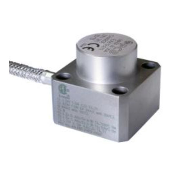
- Page 21 Model Number Revision: NR CHARGE OUTPUT ACCELEROMETER EX619A11 ECN #: 44641 Performance ENGLISH OPTIONAL VERSIONS Sensitivity(± 5 %) 50 pC/g 5.1 pC/(m/s²) Optional versions have identical specifications and accessories as listed for the standard Measurement Range ± 500 g pk ±...
- Page 22 PCB Piezotronics Inc. claims proprietary rights in REVISIONS the information disclosed hereon. Neither it nor any reproduction thereof will be disclosed to others DESCRIPTION without the written consent of PCB Piezotronics Inc. RELEASED TO DRAFTING 44641 1.63 [41.4] .61 [15.5] 1.19 [30.2]...
- Page 23 DWG: 62689 REV: NR DIN: 44641...
- Page 24 DWG: 62689 REV: NR DIN: 44641...
- Page 25 DWG: 62689 REV: NR DIN: 44641...
- Page 26 DWG: 62690 REV: NR DIN: 44641...
- Page 27 DWG: 62690 REV: NR DIN: 44641...
- Page 28 DWG: 62690 REV: NR DIN: 44641...
- Page 29 PCB Piezotronics Inc. claims proprietary rights in REVISIONS the information disclosed hereon. Neither it nor any reproduction thereof will be disclosed to others DESCRIPTION without the written consent of PCB Piezotronics Inc. RELEASED TO DRAFTING 44641 SCHEDULE DRAWING NO MODIFICATIONS PERMITTED...
- Page 30 PCB Piezotronics Inc. claims proprietary rights in REVISIONS the information disclosed hereon. Neither it nor any reproduction thereof will be disclosed to others DESCRIPTION without the written consent of PCB Piezotronics Inc. -SEE SHEET 1- SCHEDULE DRAWING NO MODIFICATIONS PERMITTED WITHOUT REFERENCE TO THE...
- Page 31 September 23, 2015 Project: Date Issued: Issued to: Industrial Monitoring Instr. (IMI) A Div. of PCB Piezotronics, Inc. 3425 Walden Ave Depew, NY 14043 Attention: Jim Devine The products listed below are eligible to bear the CSA Mark shown with adjacent indicators 'C' and 'US' for Canada and US or with adjacent indicator 'US' for US only or without either indicator for Canada only.
- Page 32 70028914 184981 Certificate: Master Contract: 70028914 September 23, 2015 Project: Date Issued: Ci = 5nF T4 (-55°C to 130°C) Li = 30µH T3 (-55°C to 195°C) T2 (-55°C to 290°C) Tl (-55 °C to 440°C) Notes: • For Canadian Installations, sensor case must be bonded to ground according to Section 18-182 of the CEC, Part 1.
- Page 33 70028914 184981 Certificate: Master Contract: 70028914 September 23, 2015 Project: Date Issued: Entity Parameters Temperature Code Ui / Vmax = 30V Ii / Imax = 130mA T6 (-55°C to 80°C) Pi / Pmax = 0.8W T5 (-55°C to 95°C) Ci = 5nF T4 (-55°C to 130°C) Li = 30µH T3 (-55°C to 195°C)
- Page 34 70028914 184981 Certificate: Master Contract: 70028914 September 23, 2015 Project: Date Issued: CAN/CSA-C22.2 No. 60079-11:14 Explosive Atmospheres – Part 11: Equipment protection by intrinsic safety "i" CAN/CSA-C22.2 No. 60079-15:12 Ed. 3 Electrical apparatus for explosive gas atmospheres - Part 15: Construction, test and marking of type of protection “n”...
- Page 35 Supplement to Certificate of Compliance 70028914 184981 Certificate: Master Contract: The products listed, including the latest revision described below, are eligible to be marked in accordance with the referenced Certificate. Product Certification History Project Date Description 70028914 Sep 23, 2015 New CSA C-US certification for model EX619XYY/ MNNNZZ for the following markings: Class I, Div 1, Groups C-D,Class II, Div 1 Groups E- G,Class III Class I, Div 2, Groups A-D, Ex ia IIB T6-T1 Ga / Ex ic IIB T6-T1...
Need help?
Do you have a question about the EX619A11 and is the answer not in the manual?
Questions and answers