Table of Contents
Advertisement
REVISION B
Form No. 3315087.000 06/17
(French 3315088.000_B)
©2017 Dometic Corporation
LaGrange, IN 46761
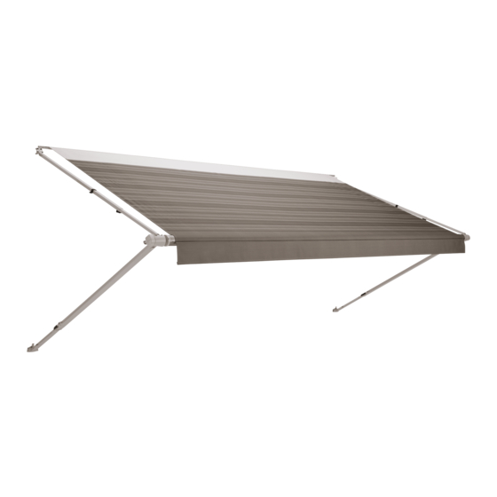
SUNCHASER
GEARED AWNING
FABRIC ROLLER TUBE ASSEMBLY (FRTA)
UNIVERSAL SERIES HARDWARE
Read these instructions carefully. These
instructions MUST stay with this product.
USA
SERVICE OFFICE
Dometic Corporation
1120 North Main Street
Elkhart, IN 46514
RECORD THIS INFORMATION FOR FUTURE
REFERENCE:
FRTA Model Number
FRTA Serial Number
Hardware Model Number
Hardware Serial Number
Date Purchased
Retailer / Qualified Installer
8500
9000
G8273000
CANADA
Dometic Corporation
46 Zatonski, Unit 3
Brantford, ON N3T 5L8
CANADA
SERVICE CENTER &
DEALER LOCATIONS
Please Visit:
www.eDometic.com
Advertisement
Table of Contents

Related Manuals for Dometic SUNCHASER 8500


Summary of Contents for Dometic SUNCHASER 8500
- Page 1 REVISION B DEALER LOCATIONS SERVICE OFFICE Dometic Corporation Form No. 3315087.000 06/17 Dometic Corporation 46 Zatonski, Unit 3 Please Visit: (French 3315088.000_B) 1120 North Main Street Brantford, ON N3T 5L8 www.eDometic.com ©2017 Dometic Corporation Elkhart, IN 46514 CANADA LaGrange, IN 46761...
-
Page 2: Table Of Contents
This awning can be installed by one person with brief help from additional personnel. Use these instructions to ensure cor- rect installation, function, and operation of product. Dometic Corporation reserves the right to modify appearances and specifications without notice. TABLE OF CONTENTS INTRODUCTION ..................................2... -
Page 3: Important Safety Instructions
IMPORTANT SAFETY INSTRUCTIONS This manual has safety information and instructions to help T he installation MUST comply with all ap- you eliminate or reduce the risk of accidents and injuries. plicable local and national codes, including the latest edition of the following standards: Recognize Safety Information U.S.A. -
Page 4: Specifications
SPECIFICATIONS Hardware Dimensions .401# .402# .405# .407# .408# MODEL G8273000 G8273000 G8273000 G8273000 *G8273000 SERIES .501# .502# .505# .507# .508# Short 64″ - 76″ (163 cm - 193 cm) 76″ - 86″ 64″ - 76″ 78″ - 91″ 94″ - 107″ Height Range (193 cm - 218 cm) (163 cm - 193 cm) -
Page 5: Prepare For Installation
PREPARE FOR INSTALLATION Installing The Door Roller And Edge Preparing The Awning Rail Guard (Optional) Make sure awning rail is parallel to RV floor, and is NOT warped or curved before in- Do NOT allow corner of entry door stalling awning fabric. -
Page 6: Determining The Awning Location
PREPARE FOR INSTALLATION 3. Place the 1/4″-20 X 1/2″ hex head screw (with I nstall the top bracket spacers if the lock washer) through the main arm and into the awning rail is too wide (has drip chan- top casting. Tighten to 65-80 in·lb torque. See nel) and interferes with the top mount- FIG. -
Page 7: Install The Awning
PREPARE FOR INSTALLATION FIG. 9 FIG. 10 Top Mounting Bracket Awning Rail With Drip Channel Top Bracket Arm Assemblies Spacer 2. Ensure the arm assemblies do not restrict use of doors, windows, etc. See FIG. 10. INSTALL THE AWNING Installing Light Switch Inserting The Awning Fabric Into The... -
Page 8: Installing The Top Mounting Brackets
INSTALL THE AWNING 3. While one person guides the awning fabric into 2. Push in one side tab of arm safety lock, then the the awning rail, carefully move (carry) the aw- other to disengage the main rafter from the main ning assembly to the predetermined location. -
Page 9: Installing The Bottom Mounting Brackets
INSTALL THE AWNING 5. ALWAYS use sealant on (clean) M ount directly into the RV floor line, over parts and surfaces where fasteners enter RV’s molding, etc. If installing over RV molding, roof and/or walls. Otherwise, water leakage a bottom spacer MUST be used. -
Page 10: Installing Stop Bolts
INSTALL THE AWNING 5. FIRE OR ELECTRICAL SHOCK FIG. 18 HAZARD. Verify there are no obstacles inside 5/16″-18 RV’s roof and/or walls (wires, pipes, etc.). Shut Lock Nut OFF gas supply, disconnect 120 Vac power from RV, and disconnect positive (+) 12 Vdc terminal from supply battery BEFORE drilling or cutting Main Arm into RV. -
Page 11: Installing The Gear Cover Assembly (Rh Side)
INSTALL THE AWNING 3. Verify alignment of the awning fabric, and proper FIG. 20 Top Casting nesting of hardware. a. If there is misalignment, adjust the arm as- sembly by loosening the back channel and Front top mounting bracket screws and move the Cover back channel accordingly. -
Page 12: Installing Cover On Lh Side
INSTALL THE AWNING Installing Cover on LH Side Connecting The LED Lights (If Applicable) Back Cover FIG. 22 S kip this subsection if the awning is NOT equipped with an LED light strip. 1. FIRE OR ELECTRICAL SHOCK HAZARD. -
Page 13: Verify The Installation
VERIFY THE INSTALLATION Testing Operation Keeping The Literature Operate the awning according to the Operating Instructions contain valuable information for prod- Instructions to verify all parts are functioning cor- uct use and consumer safety. rectly. Keep BOTH the Installation and Operat- Securing The Awning For Travel ing Instructions with product.
Need help?
Do you have a question about the SUNCHASER 8500 and is the answer not in the manual?
Questions and answers