Amazone Profihopper 1500 SmartLine Operating Instructions Manual
Self-propelled mower
Hide thumbs
Also See for Profihopper 1500 SmartLine:
- Operating instructions manual (154 pages) ,
- Original operating manual (170 pages)

Related Manuals for Amazone Profihopper 1500 SmartLine


Summary of Contents for Amazone Profihopper 1500 SmartLine
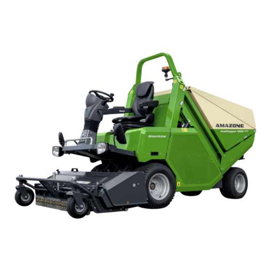
- Page 1 Operating instructions MG6399-EN-II | D.1 | 11.03.2020 Self-propelled mower Profihopper 1500 SmartLine Original operating instructions...
- Page 2 Please insert the identification data of the implement. The identification data are arranged on the rating plate.
-
Page 3: Table Of Contents
TABLE OF CONTENTS TABLE OF CONTENTS 3.5.2 Layout of the warning symbols 1 About this operating manual 3.5.3 Description of the warning symbols Meaning of the operating manual Other information on the implement Diagrams 3.6.1 Lubrication point labels 1.2.1 Warnings and signal words 3.6.2 Sound power level label 1.2.2... - Page 4 TABLE OF CONTENTS 3.20 Threaded cartridge Opening and closing the engine cover 3.21 AMAZONE cooling system - Self- 5.5.1 Opening the engine cover cleaning cooling air system 5.5.2 Closing the engine cover 4 Technical data Opening and closing the rotor...
- Page 5 TABLE OF CONTENTS 6.3.6 Adjusting the lumbar support 7.2.8 Using cruise control 6.3.7 Seat heater 7.2.9 Using the warning beacon 6.3.8 Adjusting the fore/aft isolator 7.2.10 Using the lighting for road travel 7.2.11 Actuating the horn Adjusting the armrest with 7.2.12 Using the hazard warning lights control panel...
- Page 6 TABLE OF CONTENTS 8.2.18 Cleaning the diesel tank Lubricating the machine 8.3.1 Overview of lubrication points Eliminating faults Cleaning the machine 9 Transporting the machine Loading the machine Driving the machine onto a transport vehicle Lashing the machine Towing the machine 10 Parking the machine 10.1 Parking the implement after...
-
Page 7: About This Operating Manual
1 | About this operating manual About this operating manual CMS-T-00001163-B.1 Meaning of the operating manual CMS-T-006245-A.1 The operating manual is an important document and a part of the implement. It is intended for the user and contains safety-related information. Only the instructions provided in the operating manual are reliable. -
Page 8: Further Instructions
1 | About this operating manual Diagrams DANGER Indicates a direct threat with high risk for severe physical injury, such as loss of limbs or death. WARNING Indicates a possible threat with moderate risk for severe physical injury or death. CAUTION Indicates a threat with low risk for light or moderately severe physical injuries. - Page 9 1 | About this operating manual Diagrams The specified sequence of the actions must be observed. Example: 1. Instruction 1 2. Instruction 2 1.2.3.1 Instructions and responses CMS-T-005678-B.1 Reactions to instructions are marked with an arrow. Example: 1. Instruction 1 Reaction to instruction 1 2.
-
Page 10: Lists
Your suggestions for improvement help us Technische Redaktion to create ever more user-friendly operating manuals. Postfach 51 Please send us your suggestions by post, fax or D-49202 Hasbergen email. Fax: +49 (0) 5405 501-234 E-Mail: td@amazone.de MG6399-EN-II | D.1 | 11.03.2020... -
Page 11: Safety And Responsibility
Further instructions for intended use in special cases can be requested from AMAZONE. Uses other than those specified under the intended use are considered as improper. The manufacturer is not liable for any damage resulting from improper use, solely the operator is responsible. -
Page 12: Basic Safety Instructions
2 | Safety and responsibility Basic safety instructions Basic safety instructions CMS-T-00002523-B.1 2.2.1 Safe operating organisation CMS-T-00002524-B.1 2.2.1.1 Personnel qualification CMS-T-00002525-A.1 Requirements for all persons working with the machine CMS-T-00002529-A.1 If the machine is used improperly, people can be injured or killed. To prevent accidents due to improper use, every person who works with the machine must meet the following minimum requirements:... - Page 13 2 | Safety and responsibility Basic safety instructions Skilled worker for communal or agricultural equipment CMS-T-00002527-A.1 Skilled workers for communal equipment or farmers use machines to maintain green areas and parks. They decide on the use of a machine for a specific purpose.
- Page 14 2 | Safety and responsibility Basic safety instructions Employees of the farmer, e.g. tractor driver Family members of the farmer Activity examples: Driving the machine Adjusting the mowing height 2.2.1.2 Workplaces and passengers CMS-T-00002530-B.1 Passengers Passengers can fall, be run over and severely injured or killed due to machine movements.
- Page 15 2 | Safety and responsibility Basic safety instructions 2.2.1.4 Operational safety CMS-T-00002648-B.1 Perfect technical condition CMS-T-00002649-B.1 Only use properly prepared machines Without correct preparation according to this operating manual, operational safety of the machine is not ensured. This can result in accidents and serious personal injury or even death.
- Page 16 2 | Safety and responsibility Basic safety instructions Observe the technical limit values Non-observance of the technical limits values of the machine can result in accidents and serious personal injury or even death. Moreover, the machine can be damaged. The technical limit values can be found in the Technical Data.
- Page 17 2 | Safety and responsibility Basic safety instructions Personal protective equipment CMS-T-00002651-B.1 Personal protective equipment Wearing personal protective equipment is an important safety element. Missing or unsuitable personal protective equipment increases the risk of damage to health and personal injury. Personal protective equipment includes: work gloves, safety shoes, protective clothing, breathing protection, hearing protection, face protection,...
-
Page 18: Knowing And Preventing Dangers
2 | Safety and responsibility Basic safety instructions Warning symbols CMS-T-00002652-A.1 Keep warning symbols legible Warning symbols on the machine warn you of risks in danger areas and are an important element of the machine's safety equipment. Missing warning symbols increase the risk of serious and lethal personal injury. - Page 19 2 | Safety and responsibility Basic safety instructions Liquids under pressure Escaping high pressure hydraulic fluid can penetrate into the body through the skin and cause serious personal injuries. A hole the size of a needle can already result in serious personal injuries.
-
Page 20: Machine
2 | Safety and responsibility Basic safety instructions 2.2.2.2 Danger areas CMS-T-00002655-B.1 Dangers areas on the machine The following basic dangers are encountered in the danger areas: Due to moving machine parts and implements during operation. Hydraulically raised machine parts can descend unnoticed and slowly. - Page 21 2 | Safety and responsibility Basic safety instructions 2.2.3 Safe operation and handling of the machine CMS-T-00002656-A.1 2.2.3.1 Driving safety CMS-T-00002829-A.1 Remove dirt and loose objects Loose objects that do not belong to the machine can fall off the machine or be thrown and cause personal injury.
-
Page 22: Safe Maintenance And Modification
To ensure that the operating permit remains valid in accordance with national and international regulations, use only conversion parts, spare parts and special equipment approved by AMAZONE. 2.2.4.2 Work on the machine CMS-T-00002660-A.1 Only work on the machine when it is at a... - Page 23 2 | Safety and responsibility Basic safety instructions Maintenance work Improper maintenance work endangers operational safety. This can result in accidents and serious personal injury or even death. Before you adjust, maintain or clean the machine, secure the machine. Only perform the work that is described in this operating manual.
- Page 24 2 | Safety and responsibility Basic safety instructions Danger due to welding work Improper welding work endangers the operational safety of the machine. This can result in accidents and serious personal injury or even death. Only allow qualified specialist workshops with suitably approved personnel to perform welding work on safety-relevant parts.
- Page 25 2.2.4.4 Special equipment and spare parts CMS-T-00002662-A.1 Special equipment and spare parts Special equipment and spare parts that do not meet AMAZONE requirements can impede the operational safety of the machine and cause accidents. Only use original parts or parts that meet AMAZONE requirements.
-
Page 26: Safety Routines
2 | Safety and responsibility Safety routines Safety routines CMS-T-00002673-A.1 Only work on the machine when it is at a standstill If the machine is not standing still, part can move unintentionally or the machine can be set in motion. This can result in serious injury or death. Before performing any work on the machine, shutdown and secure the machine. - Page 27 2 | Safety and responsibility Safety routines Check for safe condition Protective equipment that is not functional, faulty or removed can result in dangerous situations. Check the machine at least once a day for visible damage and check the function of the protective equipment.
-
Page 28: Product Description
3 | Product description Product description CMS-T-00002402-B.1 Implement overview CMS-T-00002409-B.1 CMS-I-00002232 MG6399-EN-II | D.1 | 11.03.2020... -
Page 29: Special Equipment
3 | Product description Special equipment Cutting deck support wheel LED marker light Cutting deck 10 Grass collector Front lighting for road travel 11 Rear wheels, steerable Exterior rearview mirror 12 Front wheels Threaded cartridge 13 Rear lights Steering wheel and controls 14 Licence plate lighting Driver's seat 15 Trailer hitch... - Page 30 3 | Product description Protective equipment Position of the safety switch Task Switches the electromagnetic coupling off if the Safety switch on the cutting deck augers are blocked or come to a standstill. 3.3.2 Roll-over protection CMS-T-00002414-A.1 If the machine tips over, the roll-over protection 1 protects the driver from injury if he is wearing his seat belt.
-
Page 31: Seat Belt
3 | Product description Protective equipment 3.3.4 Seat belt CMS-T-00002418-A.1 The seat belt 1 protects the driver in case of accidents, especially when mowing on slopes. CMS-I-00002237 3.3.5 Grass collector locking device CMS-T-00002422-B.1 The grass collector can be raised to perform maintenance on the engine or to remove blockages in the auger. -
Page 32: Transmission V-Belt Protective Cover
3 | Product description Protective equipment 3.3.6 Transmission V-belt protective cover CMS-T-00002420-B.1 The transmission V-belt protective cover 1 prevents injury from the transmission V-belt. The protective cover completely covers the transmission V-belt. CMS-I-00002235 3.3.7 Rotor protective cover CMS-T-00002421-B.1 The rotor protective cover 1 prevents injury from the rotor. -
Page 33: Rating Plate And Ce Mark
3 | Product description Rating plate and CE mark Rating plate and CE mark CMS-T-00004429-A.1 The rating plate 1 and CE mark 2 are located on the machine for identification. The vehicle ID no. 3 is additionally stamped on the front right of the machine. -
Page 34: Warning Symbols
3 | Product description Warning symbols Warning symbols CMS-T-00002408-B.1 3.5.1 Positions of the warning symbols CMS-T-00001182-B.1 CMS-I-00002250 MG6399-EN-II | D.1 | 11.03.2020... -
Page 35: Layout Of The Warning Symbols
3 | Product description Warning symbols CMS-I-00002249 3.5.2 Layout of the warning symbols CMS-T-000141-C.1 Warning symbols indicate danger areas on the machine and warn against residual dangers. In these danger areas, there are permanent or unexpected dangers. A warning symbol consists of two fields: Field 1 shows the following: A pictogram depicting the danger area, CMS-I-00000416... -
Page 36: Description Of The Warning Symbols
3 | Product description Warning symbols 3.5.3 Description of the warning symbols CMS-T-00002430-B.1 MD 075 Risk of cuts for fingers, hands, and arms As long as engine of the tractor or machine is running, stay away from the danger area. Wait until all moving parts of the machine are at a standstill before reaching into the danger area. - Page 37 3 | Product description Warning symbols MD095 Risk of accident due to non-compliance with the instructions in this operating manual Before your work on or with the implement, read and understand the operating manual. CMS-I-000138 MD 100 Risk of accidents due to improperly attached lifting gear Only attach the lifting gear at the marked positions.
- Page 38 3 | Product description Warning symbols MD 106 Risk of crushing from the machine parts unintentionally lowering Before entering the danger area, secure raised machine parts with a hydraulic or mechanical locking device. CMS-I-00000427 MD 155 Risk of accident and machine damage during transport due to improperly secured machine Only attach the lashing belts at the marked lashing positions for transporting the machine.
-
Page 39: Other Information On The Implement
3 | Product description Other information on the implement MD 244 Danger when driving on steep slopes When driving contour lines on slopes of more than 26%, the machine can tip over and seriously injure or kill the driver. Only drive contour lines on slopes of less than 26%. -
Page 40: Sound Power Level Label
3 | Product description Other information on the implement 3.6.2 Sound power level label CMS-T-00003337-A.1 The sound power level is 105 dB. CMS-I-00000445 3.6.3 Maintenance overview CMS-T-00003724-A.1 Provides an overview of the maintenance work and maintenance intervals. CMS-I-00002739 MG6399-EN-II | D.1 | 11.03.2020... -
Page 41: Functioning Of The Machine
3 | Product description Functioning of the machine The maintenance overview can be found on the inside of the radiator cover. CMS-I-00003109 Functioning of the machine CMS-T-00002432-A.1 The rotor 1 and the cutting blades installed on the rotor convey the clippings or collected material to the cross auger 2 . -
Page 42: Primo Xl Driver's Seat
3 | Product description Primo XL driver's seat Primo XL driver's seat CMS-T-00002839-B.1 Compared to the standard driver's seat, the "Primo XL" driver's seat is additionally equipped with a low frequency air suspension, longitudinal suspension, and a heater. CMS-I-00002273 3.10 Lighting and identification for road travel CMS-T-00002407-A.1 Lighting for road travel, to the rear... -
Page 43: Trailer Hitch
3 | Product description Trailer hitch 3.11 Trailer hitch CMS-T-00002841-B.1 Trailers with a ball coupling can be attached to the trailer hitch 1 . The trailer is supplied with power from the socket 2 . CMS-I-00002390 3.12 Exterior rearview mirror CMS-T-00002437-A.1 The exterior rearview mirrors 1 are only available in conjunction with the lighting. -
Page 44: Drive
3 | Product description Drive 3.13 Drive CMS-T-00002453-B.1 3.13.1 Four-wheel drive CMS-T-00002447-B.1 All four wheel are driven by electro-hydraulically controlled hydraulic motors 1 . The steered rear wheels 2 are only additionally driven if necessary. The four-wheel drive functions in forward gear and reverse gear. -
Page 45: Fuel Tank
3 | Product description Cutting deck 3.13.3 Fuel tank CMS-T-00002449-A.1 The fuel tank 1 is located on the right side and has a volume of 50 litres. CMS-I-00002260 3.14 Cutting deck CMS-T-00002405-A.1 3.14.1 Blades CMS-T-00001190-A.1 3.14.1.1 Flail blade, long H77 CMS-T-00002840-A.1 The long flail blade H77 is suitable for mowing and collecting under dry and wet conditions. -
Page 46: High Tip Emptying
3 | Product description High tip emptying 3.14.1.3 Scarifying blades CMS-T-00001193-A.1 The scarifying blades are suitable for scarifying and collecting under dry conditions. The blades are generally used in combination with cutting blades or flail blades. CMS-I-00001002 3.15 High tip emptying CMS-T-00003081-B.1 High tip emptying at up to 2.50 m enables rapid emptying on an HGV or trailer. -
Page 47: Control Elements
3 | Product description Control elements 3.17 Control elements CMS-T-00002439-B.1 3.17.1 Steering wheel CMS-T-00002455-A.1 The machine is steered by the rear wheels. The steering wheel 1 with steering knob enable comfortable one-handed steering. CMS-I-00002264 3.17.2 Operating levers and operating buttons CMS-T-00002456-A.1 CMS-I-00002262 MG6399-EN-II | D.1 | 11.03.2020... -
Page 48: Hazard Warning Light
3 | Product description Control elements Selection lever for direction of travel Operating button for lifting and lowering the cutting deck Operating lever for turn indicator and light Operating button for switching the cutting deck Operating button for the horn on and off Operating button for the warning beacon Operating button for emptying the grass collector... -
Page 49: Crank
3 | Product description Dashboard 3.17.5 Crank CMS-T-00002517-B.1 The crank 1 has the following functions: Adjusting the cutting height of the cutting deck. Open the protective cover. Remove blockages in the augers. Open and close the grass collector hood. The crank is stored and fastened in the bracket 2 on the cutting deck. -
Page 50: Engine Coolant Temperature Display
3 | Product description Dashboard 3.18.2 Engine coolant temperature display CMS-T-00002461-A.1 The engine coolant temperature display 1 shows the current temperature of the engine coolant. If the warning lamp 2 lights up, the temperature of the engine coolant is too high. CMS-I-00002266 3.18.3 Control lamps and warning lamps CMS-T-00002459-B.1... - Page 51 3 | Product description Dashboard Symbol Meaning Function Control lamp for cruise control Lights up when cruise control is switched on. Lights up when automatic regeneration of the Control lamp for exhaust temperature particle filter is active with high exhaust temperature.
-
Page 52: Buzzer
3 | Product description Dashboard 3.18.4 Buzzer CMS-T-00002463-B.1 The acoustic buzzer 1 sounds when there are warning messages, faults and when functions are executed. CMS-I-00002296 3.18.5 Info display CMS-T-00003066-B.1 3.18.5.1 Normal mode CMS-T-00002683-B.1 When the machine is being used, the normal mode is the standard display mode. - Page 53 3 | Product description Dashboard Duration of the current assignment Total worked area for the current assignment Job duration 2.7 h Collected quantity for the current assignment Job surface 560.5 m Collected volume 24 m Average speed for the current assignment Average speed 3.5 km/h Fuel consumption...
-
Page 54: Key
Special key 3 , to open the protective lid on the belt drive guard and the side cover in front of the radiator. NOTE Lost keys can be reordered from AMAZONE by CMS-I-00002360 indicating the vehicle ID no. MG6399-EN-II | D.1 | 11.03.2020... -
Page 55: Threaded Cartridge
The threaded cartridge contains the following items: Documents Aids CMS-I-00002306 3.21 AMAZONE cooling system - Self-cleaning cooling air system CMS-T-00002467-B.1 The system removes dust and plant residues from the radiator grille. Plant residues are produced particularly when mulching. The system works automatically. -
Page 56: Technical Data
4 | Technical data Technical data CMS-T-00003082-B.1 Dimensions CMS-T-00003084-B.1 CMS-I-00002305 Designation Designation Profihopper 1500 Total length 3415 mm Total height 2185 mm Height 1868 mm Ground clearance 135 mm MG6399-EN-II | D.1 | 11.03.2020... -
Page 57: Weights
4 | Technical data Weights Designation Designation Profihopper 1500 Height 2519 mm Height 2850 mm Total width 1773 mm Weights CMS-T-00003085-B.1 4.2.1 Permissible total weight CMS-T-00003086-A.1 2400 kg 4.2.2 Basic weight CMS-T-00003087-B.1 1770 kg Permissible trailer load CMS-T-00003089-B.1 Designation Value Maximum permissible trailer load 750 kg Maximum drawbar load, trailer hitch... -
Page 58: Speed
4 | Technical data Speed Speed CMS-T-00003091-B.1 4.5.1 Forward speed CMS-T-00003092-B.1 Direction of travel Forward speed Forwards max. 20 km/h Reverse max. 8 km/h 4.5.2 Working speed CMS-T-00003093-B.1 Direction of travel Working speed Forwards max. 10 km/h Tank volume CMS-T-00003094-B.1 4.6.1 Fuel tank CMS-T-00003095-B.1 Tank volume... -
Page 59: Cutting Deck
4 | Technical data Cutting deck Cutting deck CMS-T-00003097-B.1 4.8.1 Cutting dimensions CMS-T-00003098-B.1 Cutting height max. 90 mm Cutting width 1500 mm 4.8.2 Cutting tool CMS-T-00003099-A.1 NOTE The specifications of the tool quantity refers to 100% equipment with the same cutting tool. Combination of Flail blade, long Flail blade, short... -
Page 60: Noise Development Data
4 | Technical data Noise development data 4.10 Noise development data CMS-T-00003101-A.1 The workplace-related emission noise level is 88 dB(A), measured in operating condition at the ear of the tractor driver. Value of the sound power level, according to Regulation 2000/14/EC: LwA = 105 dB(A) 4.11 Vibration measurement data CMS-T-00003102-A.1... -
Page 61: Practical Routines
5 | Practical routines Practical routines CMS-T-00002855-B.1 Opening and closing the grass collector hood CMS-T-00004125-A.1 5.1.1 Opening the grass collector hood CMS-T-00004126-A.1 The grass collector hood can be opened manually to empty the grass collector manually when it is overfilled. 1. -
Page 62: Closing The Grass Collector Hood
5 | Practical routines Opening and closing the grass collector hood To unlock the grass collector hood, pull the hooks 1 on the right and left to the rear with the crank 2 up to the stop. 4. Swivel the grass collector hood 3 upwards using the gas springs. -
Page 63: Opening And Closing The Seat
5 | Practical routines Opening and closing the seat carrier 4. Push the crank 1 down into the bracket using the handle 2 until the safety clip 3 engages. 5. Check that the crank is properly locked. CMS-I-00002315 Opening and closing the seat carrier CMS-T-00002856-B.1 5.2.1 Opening the seat carrier CMS-T-00002853-B.1... -
Page 64: Closing The Seat Carrier
5 | Practical routines Opening the toolbox 1. Insert the key 1 in the lock 2 . To unlock the seat carrier, turn the key to the left. 3. Swivel the seat carrier 3 up using the handle 4 with help of the gas spring. The gas spring and the weight of the seat carrier keep the seat carrier in the open position. -
Page 65: Closing The Toolbox
5 | Practical routines Closing the toolbox 1. Open the protective cap 1 . 2. Using the key 2 , unlock the toolbox 3 . 3. Open the toolbox 3 by hand in the area of the hollow. CMS-I-00002359 Closing the toolbox CMS-T-00002948-A.1 1. - Page 66 5 | Practical routines Opening and closing the engine cover CAUTION Risk of burn injuries due to hot surfaces on the engine and exhaust system When the engine and exhaust system are hot, keep the engine cover closed. Through the engine cover, the following components can be accessed: Diesel engine Engine oil filling opening...
-
Page 67: Closing The Engine Cover
5 | Practical routines Opening and closing the engine cover WARNING Risk of injury due to defective gas springs When the motor cover is open, check the hold of the motor cover. Support the motor cover only using the gas spring. Replace defective gas springs immediately. -
Page 68: Opening And Closing The Rotor Protective Cover
5 | Practical routines Opening and closing the rotor protective cover WARNING Risk of crushing when lowering the grass collector Serious injuries or even death are possible. Only lower the grass collector when nobody is standing in the danger area. While lowering, do not put any limbs in the bracket for the grass collector. - Page 69 5 | Practical routines Opening and closing the rotor protective cover 1. Completely lower the cutting deck. 2. Pull the safety hook 1 to the front. 3. Take out the crank 2 . CMS-I-00002314 4. Put the crank 1 on the three locking mechanisms 2 .
-
Page 70: Closing The Rotor Protective Cover
5 | Practical routines Opening and closing the rotor protective cover 5.6.2 Closing the rotor protective cover CMS-T-00002860-B.1 1. Hold the rotor protective cover 1 by the handle 2. Unhook the rope 3 . 3. Close the rotor protective cover. CMS-I-00002354 4. -
Page 71: Opening And Closing The Radiator Cover
Oil cooler Air filter Engine oil dipstick Hydraulic oil tank AMAZONE cooling system fan 1. Insert the special key 1 in the lock 2 . 2. Turn the special key to the left. The radiator cover is unlocked. 3. Open the radiator cover 3 by hand with help of the gas spring. -
Page 72: Opening And Closing The Electrical System Maintenance Flap
5 | Practical routines Opening and closing the electrical system maintenance flap Opening and closing the electrical system maintenance flap CMS-T-00002863-B.1 5.8.1 Opening the electrical system maintenance flap CMS-T-00002624-B.1 Through the electrical system maintenance flap, the following components can be accessed: Fuse box and relays Machine computer Diagnosis plug for workshop work... -
Page 73: Preparing The Machine
6 | Preparing the machine Preparing the machine CMS-T-00003056-B.1 Adjusting the standard driver's seat CMS-T-00002533-B.1 6.1.1 Selecting the longitudinal setting CMS-T-00002552-B.1 1. Press and hold the lever 1 outwards. 2. Push the seat into the desired position. 3. Let go of the lever. The lever engages perceptibly and audibly. -
Page 74: Adjusting The Backrest
6 | Preparing the machine Adjusting the standard driver's seat 6.1.2 Adjusting the backrest CMS-T-00002554-B.1 1. Pull the lever 1 up and hold it. 2. Move the backrest to the desired position 3. Let go of the lever. The lever engages perceptibly and audibly. The backrest is locked in the desired position. -
Page 75: Adjusting The Armrests
6 | Preparing the machine Adjusting the standard driver's seat 6.1.4 Adjusting the armrests CMS-T-00002548-B.1 The slant of the armrests can be adjusted using the hand wheel 1 . To raise the armrest turn the hand wheel outwards To lower the armrest turn the hand wheel inwards. -
Page 76: Adjusting The Deluxe Driver's Seat
6 | Preparing the machine Adjusting the Deluxe driver's seat Adjusting the Deluxe driver's seat CMS-T-00002551-B.1 6.2.1 Selecting the longitudinal setting CMS-T-00002549-B.1 1. Pull the lever 1 up and hold it. 2. Push the seat into the desired position. 3. Let go of the lever. The lever engages perceptibly and audibly. -
Page 77: Setting The Driver's Weight For The Air Suspension
6 | Preparing the machine Adjusting the Deluxe driver's seat 6.2.3 Setting the driver's weight for the air suspension CMS-T-00002557-B.1 For proper functioning of the air suspension, the weight of the respective driver must be set while the driver's seat is occupied. The weight can be set from 45 kg to 170 kg. -
Page 78: Adjusting The Headrest
6 | Preparing the machine Adjusting the Deluxe driver's seat 6.2.5 Adjusting the headrest CMS-T-00002559-B.1 To adjust the height of the headrest pull out or push in the headrest over the perceptible increments. To remove the headrest, Pull the headrest out with a jerk beyond the top end stop. -
Page 79: Adjusting The Primo Xl Driver's Seat
6 | Preparing the machine Adjusting the Primo XL driver's seat Adjusting the Primo XL driver's seat CMS-T-00003068-B.1 6.3.1 Selecting the longitudinal setting CMS-T-00002549-B.1 1. Pull the lever 1 up and hold it. 2. Push the seat into the desired position. 3. -
Page 80: Setting The Driver's Weight For The Air Suspension
6 | Preparing the machine Adjusting the Primo XL driver's seat 6.3.3 Setting the driver's weight for the air suspension CMS-T-00002557-B.1 For proper functioning of the air suspension, the weight of the respective driver must be set while the driver's seat is occupied. The weight can be set from 45 kg to 170 kg. -
Page 81: Adjusting The Headrest
6 | Preparing the machine Adjusting the Primo XL driver's seat 6.3.5 Adjusting the headrest CMS-T-00002559-B.1 To adjust the height of the headrest pull out or push in the headrest over the perceptible increments. To remove the headrest, Pull the headrest out with a jerk beyond the top end stop. -
Page 82: Adjusting The Fore/Aft Isolator
6 | Preparing the machine Adjusting the armrest with control panel 6.3.8 Adjusting the fore/aft isolator CMS-T-00002852-B.1 To switch on the fore/aft isolator, set the handle to position 1 . To switch off the fore-aft isolator, set the handle to position 2 . CMS-I-00002448 Adjusting the armrest with control panel CMS-T-00002550-B.1... -
Page 83: Adjusting The Steering Column
6 | Preparing the machine Adjusting the steering column 7. Loosen the locking bolt 1 . 8. Adjust the slant of the armrest 2 . 9. Tighten the locking bolt. CMS-I-00002331 Adjusting the steering column CMS-T-00002534-A.1 1. Loosen the clamping lever 1 . 2. -
Page 84: Refilling The Engine Oil
6 | Preparing the machine Refilling the engine oil 3. Read the engine oil level 1 . The correct oil level lies between the minimum 2 and maximum 3 marks. If the engine oil level is below the minimum level, refill the engine oil. -
Page 85: Refilling The Hydraulic Oil
6 | Preparing the machine Refilling the hydraulic oil 3. Open the radiator cover 1 . 4. Check the hydraulic oil level on the fill level indicator 2 of the oil tank. The hydraulic oil level is optimal when the level reaches the upper mark 3 . -
Page 86: Refuelling Diesel
6 | Preparing the machine Refuelling diesel 6.11 Refuelling diesel CMS-T-00002616-B.1 IMPORTANT Machine damage due to incorrect or insufficient fuel. Only use diesel fuels with a sulphur content ≤ 10 mg/kg, according to the standards DIN 51628 und EN 590. Do not use biodiesel or other fuel mixtures. -
Page 87: Checking The Blades And Blade Mounts
6 | Preparing the machine Checking the blades and blade mounts 6.13 Checking the blades and blade mounts CMS-T-00002680-B.1 WARNING Rotor still running Risk of drawing in and cutting injuries As long as the rotor and cutting tools are moving, keep the rotor protective cover closed. - Page 88 6 | Preparing the machine Selecting the blades Flail blade, Flail blade, Flail blade, Application Scarifying Scarifying long H77 with short H60 with long H77, area blade 3 mm blade 2 mm scarifying scarifying standard blade blade CMS-I-00002320 CMS-I-00002320 CMS-I-00002322 CMS-I-00002321 CMS-I-00002323 Grass court...
-
Page 89: Changing Or Replacing The Blades
6 | Preparing the machine Changing or replacing the blades 6.15 Changing or replacing the blades CMS-T-00002537-B.1 WARNING Rotor still running Risk of drawing in and cutting injuries As long as the rotor and cutting tools are moving, keep the rotor protective cover closed. 1. -
Page 90: Installing The Mulch Flap
6 | Preparing the machine Installing the mulch flap 4. Push in a different or new blade with the open side on the pointed area and swivel the blade on the mount. 5. Close the rotor protective cover. 6.16 Installing the mulch flap CMS-T-00002639-B.1 The machine is equipped with a mulch flap. -
Page 91: Adjusting The Cutting Height
6 | Preparing the machine Adjusting the cutting height 3. Take the mulch flap out of the cutting deck. 4. Clean the mulch flap. 5. Close the rotor protective cover. 6. Put the mulch flap 1 on the rotor protective cover. -
Page 92: Folding Up The Roll-Over Protection
6 | Preparing the machine Folding up the roll-over protection 5. Push the crank 1 down into the bracket using the handle 2 until the locking mechanism 3 engages. 6. Check that the crank is properly locked. CMS-I-00002315 6.19 Folding up the roll-over protection CMS-T-00002547-B.1 CAUTION Risk of crushing hands when folding the... -
Page 93: Folding Down The Roll-Over Protection
6 | Preparing the machine Folding down the roll-over protection 6. Check that the roll-over protection is securely locked. 7. Adjust the driver's seat. 6.20 Folding down the roll-over protection CMS-T-00002546-B.1 WARNING Risk of crushing when the roll-over protection is always folded down The driver can be injured or even killed if the machine tips over Only fold down the roll-over protection... -
Page 94: Coupling The Trailer
6 | Preparing the machine Coupling the trailer 3. Pull out the locking levers 1 , on the left and right, and turn to the right up to the stop. The locking lever is locked when it is in the open position. - Page 95 6 | Preparing the machine Preparing the machine for road travel 5. Check the warning beacon for proper function. 6. Repair defective warning beacon immediately. 7. Completely empty the grass collector. 8. Remove loose clippings on the cutting deck. 9. Raise the cutting deck completely. MG6399-EN-II | D.1 | 11.03.2020...
-
Page 96: Using The Machine
7 | Using the machine Using the machine CMS-T-00003058-B.1 Climbing on and off CMS-T-00002666-A.1 To climb on and off, use the handle 1 and the steps 2 . 2. Always climb up and down facing the machine. CMS-I-00002386 Driving the machine CMS-T-00003073-B.1 7.2.1 Using the seat belt CMS-T-00002627-B.1... -
Page 97: Starting The Diesel Engine
7 | Using the machine Driving the machine 1. Pull the seat belt by the belt tongue 1 over your hips. 2. Press the belt tongue into the belt buckle 2 . When the belt tongue engages audibly, the seat belt is locked. -
Page 98: Switching Off The Diesel Engine
7 | Using the machine Driving the machine 4. Insert the ignition key 1 into the ignition lock. 5. Turn the ignition key to position The steering wheel lock is unlocked. 6. Turn the ignition key to position The ignition is switched on. The diesel engine preheats. -
Page 99: Selecting The Direction Of Travel
7 | Using the machine Driving the machine 7.2.4 Selecting the direction of travel CMS-T-00002629-B.1 1. Sit on the driver's seat. To drive forwards, lift the selection lever 1 and move to position To drive in reverse, lift the selection lever and move to position 3 . CMS-I-00002370 move the selection lever to the neutral position 7.2.5 Accelerating... -
Page 100: Applying The Parking Brake
7 | Using the machine Driving the machine 7.2.7 Applying the parking brake CMS-T-00002633-B.1 1. Step on the brake pedal 1 . 2. Actuate the locking lever 2 . 3. Release the brake pedal. The parking brake is active and the control lamp lights up. -
Page 101: Using The Warning Beacon
7 | Using the machine Driving the machine 7.2.8.2 Switching cruise control off CMS-T-00002866-B.1 1. Press the operating button once. Cruise control is switched off and the control lamp is turned off. The driving speed is controlled manually with the accelerator pedal again. To call up the previously saved speed, switch cruise control back on. -
Page 102: Using The Lighting For Road Travel
7 | Using the machine Driving the machine 7.2.10 Using the lighting for road travel CMS-T-00002634-B.1 To switch on the parking lights, turn the rotary switch to position To switch on the dipped headlights, turn the rotary switch to position To switch off the lighting for road travel, turn the rotary switch to position CMS-I-00002362... -
Page 103: Actuating The Horn
7 | Using the machine Using the implement 7.2.11 Actuating the horn CMS-T-00002646-B.1 Press the operating button 1 . The horn is sounded as long as the button is pressed. CMS-I-00002363 7.2.12 Using the hazard warning lights CMS-T-00002647-B.1 With the switch 1 , the hazard warning lights are switched on off. -
Page 104: Stopping Mowing
7 | Using the machine Using the implement REQUIREMENTS The driver is sitting on the driver's seat The parking brake is released The grass collector is closed and completely lowered The grass collector is not completely full To lower the cutting deck, Press the button. -
Page 105: Mulching
7 | Using the machine Using the implement DANGER Rotor still running and ejected objects Serious injuries or even death are possible Only raise the cutting deck when the rotor is standing still. To raise the cutting deck, Press the button. -
Page 106: Emptying The Grass Collector
7 | Using the machine Emptying the grass collector Emptying the grass collector CMS-T-00003076-B.1 7.4.1 Emptying the grass collector close to the ground CMS-T-00002641-B.1 1. Completely lower the grass collector. 2. Drive the machine in reverse towards the unloading point. To tip the grass collector, press the button. - Page 107 7 | Using the machine Emptying the grass collector 1. Drive the machine in reverse up to 1 m before the unloading point. NOTE The maximum height for high tip emptying is 2.50 2. Raise the grass collector by pressing the button.
-
Page 108: Setting The Info Display
7 | Using the machine Setting the Info display 6. Lower the grass collector by pressing the button. The buzzer sounds and the control lamp lights up until the grass collector is completely lowered. CMS-I-00002379 Setting the Info display CMS-T-00003077-B.1 7.5.1 Setting the language CMS-T-00002686-B.1 1. -
Page 109: Setting The Clock
7 | Using the machine Setting the Info display 7.5.2 Setting the clock CMS-T-00002687-B.1 1. Sit on the driver's seat. 2. Switch on the ignition. 3. Press and hold the operating buttons 1 and 2 for 3 seconds. 4. Set the time with the buttons . 5. -
Page 110: Resetting The Maintenance Interval
7 | Using the machine Setting the Info display 7.5.5 Resetting the maintenance interval CMS-T-00002757-B.1 NOTE The maintenance interval may only be reset by a specialist workshop after maintenance has been performed. REQUIREMENTS The grass collector is slightly raised, the control lamp lights up. -
Page 111: Repairing The Machine
8 | Repairing the machine Repairing the machine CMS-T-00002721-B.1 Lifting the machine CMS-T-00002758-B.1 Lifting points on the machine are indicated with stickers. IMPORTANT Mchine damage due to incorrect positioning the jack or lifting equipment Position the jack or lifting equipment only in the marked area on the frame. -
Page 112: Maintaining The Machine
8 | Repairing the machine Maintaining the machine Maintaining the machine CMS-T-00002740-B.1 8.2.1 Maintenance schedule after the first working run Checking the wheel bolt tightening torques see page 109 Checking the hydraulic hoses see page 110 all 10 Operating hours / daily Checking the engine coolant fill level see page 107 Cleaning the radiator... -
Page 113: Checking The Engine Coolant Fill Level
8 | Repairing the machine Maintaining the machine 8.2.2 Checking the engine coolant fill level CMS-T-00002747-B.1 INTERVAL all 10 Operating hours daily 1. Open the seat carrier. 2. Open the bottom maintenance flap 1 by hand on the opening 2 . CMS-I-00002357 3. -
Page 114: Cleaning The Radiator
8 | Repairing the machine Maintaining the machine 8.2.3 Cleaning the radiator CMS-T-00002749-B.1 INTERVAL all 10 Operating hours daily 1. Open the radiator cover. 2. Blow out the radiator fins 1 with compressed air. 3. Close the radiator cover. CMS-I-00002436 8.2.4 Checking the water separator CMS-T-00002751-B.1 INTERVAL... -
Page 115: Cleaning The Water Separator
8 | Repairing the machine Maintaining the machine 8.2.5 Cleaning the water separator CMS-T-00002846-B.1 INTERVAL all 50 Operating hours weekly 1. Open the seat carrier. 2. Slide a hose onto the hose nipple 1 . 3. Route the other end of the hose to a suitable collection bucket. -
Page 116: Checking The Hydraulic Hoses
8 | Repairing the machine Maintaining the machine 8.2.7 Checking the hydraulic hoses CMS-T-00002750-B.1 INTERVAL after the first working run all 50 Operating hours weekly NOTE The hydraulic hoses can be reached through the following access points: Engine cover Seat carrier Under the raised grass collector CMS-I-00000532 1. - Page 117 8 | Repairing the machine Maintaining the machine Belt tension upon initial Drive belt Belt tension after running in installation Main drive belt 380 N - 430 N 330 N - 380 N Fan drive belt 250 N - 300 N 200 N - 250 N Cutting deck drive belt 380 N - 430 N...
- Page 118 8 | Repairing the machine Maintaining the machine 15. Damaged and worn drive belts must be immediately replaced by a specialist workshop. 16. Close the seat carrier. 17. Remove the protective cover 1 . 18. Check the belt tension on all 5 rotor drive belts 19.
-
Page 119: Cleaning The Air Filter
8 | Repairing the machine Maintaining the machine 8.2.9 Cleaning the air filter CMS-T-00002845-B.1 INTERVAL all 50 Operating hours weekly 1. Open the radiator cover. 2. Open the locking mechanisms 1 . 3. Remove the air filter lid 2 . CMS-I-00002412 4. -
Page 120: Changing The Air Filter
8 | Repairing the machine Maintaining the machine 8.2.10 Changing the air filter CMS-T-00002849-B.1 INTERVAL all 500 Operating hours every 12 months 1. Open the radiator cover. 2. Open the locking mechanisms 1 . 3. Remove the air filter lid 2 . CMS-I-00002412 4. -
Page 121: Checking The Battery
8 | Repairing the machine Maintaining the machine 8.2.11 Checking the battery CMS-T-00002744-B.1 INTERVAL all 500 Operating hours every 12 months 1. Open the seat carrier. 2. Check the voltage of the battery 1 at rest. Voltage Battery status The battery is fully 12.65 V - 12.8 V charged. -
Page 122: Replacing The Drive Belt
8 | Repairing the machine Maintaining the machine 8.2.12 Replacing the drive belt CMS-T-00002843-B.1 INTERVAL all 500 Operating hours every 12 months IMPORTANT Risk of machine damage. Only have the drive belts replaced or adjusted by a qualified specialist workshop. 1. -
Page 123: Changing The Hydraulic Oil And Filter
8 | Repairing the machine Maintaining the machine 4. Replace all 5 drive belts 1 . CMS-I-00002919 5. Replace all 3 drive belts 1 . CMS-I-00002918 8.2.13 Changing the hydraulic oil and filter CMS-T-00002748-B.1 INTERVAL all 500 Operating hours every 12 months 1. -
Page 124: Changing The Engine Oil And Oil Filter
8 | Repairing the machine Maintaining the machine The contamination indicator 1 shows the degree of contamination of the hydraulic oil filter. 4. Open the radiator cover. 5. Unscrew the lid 2 . 6. Remove the filter insert. 7. Put in a new filter insert. 8. -
Page 125: Changing The Water Separator Filter Insert
8 | Repairing the machine Maintaining the machine 1. Always replace the oil filter 1 when changing the oil. 2. Drain the engine oil through the drain screw 2 into a suitable collection bucket. 3. Dispose of the engine oil in an environmentally friendly manner. -
Page 126: Changing The Fuel Filter
8 | Repairing the machine Maintaining the machine 8.2.16 Changing the fuel filter CMS-T-00002850-B.1 INTERVAL all 500 Operating hours every 12 months IMPORTANT Risk of machine damage Only have work on the engine and its components performed by a qualified specialist workshop. -
Page 127: Cleaning The Diesel Tank
8 | Repairing the machine Maintaining the machine 8.2.18 Cleaning the diesel tank CMS-T-00002844-B.1 INTERVAL all 500 Operating hours every 12 months IMPORTANT Risk of machine damage Only have work on the engine and its components performed by a qualified specialist workshop. -
Page 128: Lubricating The Machine
8 | Repairing the machine Lubricating the machine Lubricating the machine CMS-T-00002734-A.1 8.3.1 Overview of lubrication points CMS-T-00002735-A.1 CMS-I-00002426 all 10 Operating hours / daily CMS-I-00002424 MG6399-EN-II | D.1 | 11.03.2020... - Page 129 8 | Repairing the machine Lubricating the machine all 50 Operating hours / weekly CMS-I-00002422 CMS-I-00002421 CMS-I-00002427 CMS-I-00002425 CMS-I-00002423 MG6399-EN-II | D.1 | 11.03.2020...
-
Page 130: Eliminating Faults
8 | Repairing the machine Eliminating faults Eliminating faults CMS-T-00002723-B.1 Error code Error Cause Solution Defective lighting for road Lamp or lighting supply line is see page 127 travel damaged. Defective fuse see page 127 Fault warning lamp is lit There is a fault on the see page 128 machine... - Page 131 8 | Repairing the machine Eliminating faults Error code Error Cause Solution 4233, 4234 Fault on the rotor switch Stop working with the Rotor switch error machine immediately. appears Have the fault eliminated by a qualified specialist workshop. 4235, 4236 Cruise control switch error Fault on the cruise control Stop working with the...
- Page 132 8 | Repairing the machine Eliminating faults Error code Error Cause Solution 4216 Fault on the seat switch Stop working with the Seat switch error machine immediately. appears Have the fault eliminated by a qualified specialist workshop. 6251 Warning lamp for hydraulic oil The hydraulic oil level is too see page 131 level...
- Page 133 8 | Repairing the machine Eliminating faults 8.4.1 Defective lighting for road travel CMS-T-00002723-B.1 Lamp or lighting supply line is damaged. NOTE Only the lamps for the front headlights can be replaced. All other lights are equipped with LED lamps. Position Designation Lamp...
- Page 134 8 | Repairing the machine Eliminating faults Rated Position Fuse current EGR valve 20 A Machine 20 A control unit Machine 20 A control unit Ignition 20 A Engine 20 A CMS-I-00002389 control unit 4. Replace defective fuses. 5. Push the cover onto the fuse box. 6.
- Page 135 8 | Repairing the machine Eliminating faults 8.4.4 8506: Blockage on the cutting deck, warning lamp is lit. CMS-T-00002723-B.1 A foreign object or clippings are blocking the cross auger 1. Open the rotor protective cover. 2. Unlock the locking mechanism 1 with the special key.
- Page 136 8 | Repairing the machine Eliminating faults 3. Switch off the engine. 4. Remove the ignition key. 5. Apply the parking brake. 6. Take the crank 1 out of the bracket on the cutting deck. 7. Push the bent part of the crank through the hole in the feed auger 2 .
- Page 137 8 | Repairing the machine Eliminating faults 8.4.5 6251: Warning lamp for hydraulic oil level is lit CMS-T-00002723-B.1 The hydraulic oil level is too low 1. Stop working with the machine immediately. 2. Check the hydraulic oil level. 3. refill the hydraulic oil. 8.4.6 4213: Hydraulic oil temperature error message appears CMS-T-00002723-B.1...
-
Page 138: Cleaning The Machine
8 | Repairing the machine Cleaning the machine Cleaning the machine CMS-T-00002722-B.1 IMPORTANT Risk of machine damage due to cleaning jet of the high-pressure nozzle Never direct the cleaning jet of the high- pressure cleaner or hot water high- pressure cleaner onto the marked components. -
Page 139: Transporting The Machine
9 | Transporting the machine Transporting the machine CMS-T-00002694-B.1 Loading the machine CMS-T-00002737-B.1 The machine has 2 attachment points for slings. WARNING Risk of accidents due to improperly attached lifting gear If the lifting gear is not attached at suitable positions, the machine or components can be damaged during loading and endanger safety. -
Page 140: Driving The Machine Onto A Transport Vehicle
9 | Transporting the machine Driving the machine onto a transport vehicle Driving the machine onto a transport vehicle CMS-T-00002738-B.1 WARNING Danger when loading and transporting the machine Risk of serious injuries Do not drive the machine onto a transport vehicle when on a slope or incline. -
Page 141: Towing The Machine
9 | Transporting the machine Towing the machine 1. Only attach lashing straps at the marked points. To attach the lashing straps to the machine, use the bottom holes. 3. Secure the machine in accordance with the regulations to the transport vehicle. CMS-I-00003108 Towing the machine CMS-T-00002707-B.1... - Page 142 9 | Transporting the machine Towing the machine 4. Attach the towline to the towing eye 1 . 5. After towing, close the bypass valve again. 6. After towing, apply the parking brake. CMS-I-00002430 MG6399-EN-II | D.1 | 11.03.2020...
-
Page 143: Parking The Machine
10 | Parking the machine Parking the machine CMS-T-00002695-B.1 10.1 Parking the implement after operation CMS-T-00003942-A.1 1. Completely empty the grass collector and lower it completely. 2. Completely lower the cutting deck. IMPORTANT Fire hazard Remove grass residues in the area of the engine and exhaust system. - Page 144 10 | Parking the machine Preparing the machine for longer periods of standstill or overwintering 9. Make sure that there is enough antifreeze in the engine cooling system. 10. Store the machine in a dry place. MG6399-EN-II | D.1 | 11.03.2020...
-
Page 145: Appendix
11 | Appendix Appendix CMS-T-00002703-B.1 11.1 Bolt tightening torques CMS-T-00000373-B.1 CMS-I-000260 NOTE Unless specified otherwise, the bolt tightening torques listed in the table apply. 10.9 12.9 M8x1 16(17) M10x1 18(19) M12x1.5 M 14x1.5 M16x1.5 M18x1.5 M20x1.5 MG6399-EN-II | D.1 | 11.03.2020... -
Page 146: Other Applicable Documents
11 | Appendix Other applicable documents 10.9 12.9 M22x1.5 1050 1000 1200 M24x2 1100 1300 1050 1500 1800 M27x2 1150 1600 1950 1450 2000 2400 M30x2 1600 2250 2700 CMS-I-00000065 20.4 40.7 70.5 11.2 Other applicable documents CMS-T-00002704-A.1 Yanmar diesel engine operating manual MG6399-EN-II | D.1 | 11.03.2020... -
Page 147: Indexes
12 | Indexes Indexes 12.1 GLOSSARY CMS-T-00002705-B.1 4WDi This is what the machine's intelligent four-wheel drive is called. CAN is the abbreviation for Controller Area Network. CAN bus designates the standard network in which all electronic components communicate with each other. -
Page 148: Index
Adjusting the cutting height Engine cover Radiator cover 65, 65 Adjusting the steering column Seat carrier Aids Toolbox 58, 59 AMAZONE cooling system Crank Armrest with control panel Cross auger adjustment Eliminating blockages Cruise control switching off Blades switching on... - Page 149 12 | Indexes INDEX Diesel engine Fuel tank starting Faults switching off Blockage on the cutting deck Cross auger is blocked Diesel fuel tank Eliminating blockages in the feed auger Refuelling diesel Engine overheating error message Dimensions Fault warning lamp Hydraulic oil level warning lamp Direction of travel Hydraulic system temperature error message 131...
- Page 150 12 | Indexes INDEX Applying the parking brake Replacing the drive belt Overview Mowing Parking brake Switching on the cutting deck slowing down starting Switching on the ignition Operating button Info display Cruise control Error message display Cutting deck Job mode display Hazard warning light Maintenance interval display Warning beacon...
- Page 151 12 | Indexes INDEX Protective equipment Exterior rearview mirror Chain guard Primo XL driver's seat Grass collector locking device Standard driver's seat Roll-over protection Adjusting the armrests Rotor protective cover Adjusting the backrest Safety switch Adjusting the headrest Seat belt Adjusting the seat suspension Transmission V-belt protective cover Selecting the longitudinal setting...
- Page 152 12 | Indexes INDEX Lashing the machine Loading the machine Tyre dimensions Tyre inflation pressure checking Tyres Inflation pressure Using the hazard warning lights Using the machine Climbing on and off Emptying the grass collector High tip emptying of the grass collector Info display Rotor protective cover 62, 64...
- Page 154 AMAZONE S.A. FORBACH 17, rue de la Verrerie BP 90106 57602 Forbach Cedex France +33 (0)3 87 84 65 70 forbach@amazone.fr www.amazone.fr...
Need help?
Do you have a question about the Profihopper 1500 SmartLine and is the answer not in the manual?
Questions and answers