Advertisement
Quick Links
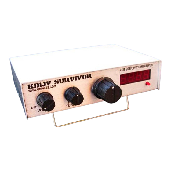
Controls: Controls consist of Volume, Fine and Main (course) tuning.
Volume:
Set the volume control to a comfortable listening level. The AGC will hold the audio level to this volume for all but the weakest signals. The
AGC has a slightly delayed response to keep it from overshooting when a large signal appears. This results in a momentary "thump". Without
the slight delay, all audio would be lost until the AGC could recover from overshooting, which could take several seconds.
Main tuning:
Main tuning has about a 350 kHz range in a single turn of the knob. NOTE: Tuning is "backwards". Turning the tuning knob clockwise
decreases frequency.
Fine tuning:
The fine tuning control has about a 30 kHz range, allowing you to tune between several near-by stations and to compensate for any minor
drift the VFO has during operation.
Microphone: An "electret" microphone element is required. The rig supplies the power needed for the mic. A suitable, low cost microphone is
available from www.QRPKITS.com
Push To Talk (PTT):
Transmitting is initiated by pushing the PTT button on the microphone and then talking (duh). The PTT switch is also used to activate "tune"
and "CW" modes.
Tune up mode:
Most 75/80 meter antennas have a fairly narrow bandwidth so therefore require an antenna tuner which needs to be readjusted every so
often as you move up or down the band. Since a steady carrier works better then whistling into the mike to get a signal, a steady carrier or
"tune mode" is built into the rig.
Tune mode is activated by:
1.
A very short push and release of the PTT switch on the microphone, < 1/2 second.
2.
A "beep" will sound in the audio output, announcing the tune mode is now active.
3.
Using the PTT will now activate a 600 Hz tone which is injected into the microphone circuit to modulate the rig. The tone is also
heard in the speaker when the rig is transmitting. Transmit power is typically about 5 watts in tune mode, but will vary depending
on the microphone gain setting.
4.
To exit Tune mode, perform another very short push and release the PTT switch.
5.
A double beep will sound in the audio output to announce the tune mode is no longer active.
CW [Morse] mode:
The Survivalist can be operated in CW mode thanks to the Tune mode and microprocessor control of the T/R sequencing in the transceiver.
The difference between CW and Tune mode is that in CW mode, the transceiver must respond to quick changes in the state of the PTT
switch and stay in the CW mode. Once enabled, CW mode can only be cleared by turning the rig off, then back on again.
CW mode is enabled by keying the character "H" with the PTT at between 5 and 20 wpm. This allows activating CW mode with either a
straight key or external paddle. There will be no annunciating side tone until CW mode is enabled, so you have to mentally count the key
taps to enter the mode. If not enough pulses are detected, the rig may enter Tune mode instead of CW mode. There just has to be four on/off
pulses detected in less than ½ second to enter CW mode. When CW mode is detected and enabled, the audio output will annunciate "CW".
The Survivalist will now operate as a CW transceiver, allowing for cross mode communication in the phone band.
SurvivorB1_20171113
"The Survivor"
A 80 meter QRP SSB transceiver
Operation:
●
Up to 10 watts pep @ 13.8V
●
0.2 uV receiver sensitivity
●
Up to 350 kHz receiver tuning range
●
200 Hz warm up drift. (stable room temperature)
●
8 ohm 500 mw speaker output.
●
"Tune" and CW modes
●
50 ma Rx current (with optional Digital Dial)
●
small size 6" x 4" x 1.5", 11.5oz.
●
13.8V at 2A min recommended power supply
1
Advertisement

Related Manuals for QRPKits KD1JV Survivor


Summary of Contents for QRPKits KD1JV Survivor
- Page 1 VFO has during operation. Microphone: An “electret” microphone element is required. The rig supplies the power needed for the mic. A suitable, low cost microphone is available from www.QRPKITS.com Push To Talk (PTT): Transmitting is initiated by pushing the PTT button on the microphone and then talking (duh). The PTT switch is also used to activate “tune”...
- Page 2 Parts placement diagram, color coded. The picture below illustrates how a well constructed board should look like. SurvivorB1_20171113...
- Page 3 Parts list: VALUE Markings/type 5.6 ohms GRN/BLU/GLD/GLD All resistors are 1/4w, 5% CARBON FILM 10 ohms BRN/BLK/BLK/GLD 51 ohms GRN/BRN/BLK/GLD this value is easy to mix up with 1 Meg – same colors, reverse order. 100 ohms BRN/BLK/BRN/GLD 220 ohms RED/RED/BRN/GLD 470 ohms YEL/VOL/BRN/GLD...
- Page 4 2N7000 MOSFET TO-92 IRF510PBF Power mosfet TO-220 78L05 5V, 100 ma regulator 1N4148 SS diode 1N5231B 5.1V zener 1N4756B 47 V 1W zener 1N5817 1A shottky diode SA612A or SA602 8 pin DIP mixer/osc LM358N 8 pin DIP dual op amp LM386N 8 pin DIP Audio amp 74HC4053N...
- Page 5 Print this large, ink jet printer friendly parts placement and value diagram for easy reference during assembly. Experienced builders will likely only need this diagram to stuff most of the board, but review the assembly instructions for any notes. SurvivorB1_20171113...
- Page 6 Assembly tips: ● Presort the various parts and place similar types in small paper picnic bowls. Resistors in one, capacitors in another, and so on. This will not only speed assembly, but will also help keep parts from getting lost. If you like, you can also cross check the parts against the parts list as you do this to make sure you have them all.
- Page 7 Resistor, RFC and Diode placement ● Caution: The 1N4148 and 1N5231 diodes look identical, read the numbers carefully on the side of the part. A magnifying glass maybe required. Observe polarity as indicated by black line on one end of the part and diagram. ●...
- Page 8 Sockets, crystals, trimmer resistors and DC power connector: ● Parts to be installed are highlighted in gray in diagram below. ● Install crystals. Push flush to board. ○ Use resistor lead clippings to solder top edge of X1 through X5 to the solder pad next to the top of can. ●...
- Page 9 Capacitors The numbers on the small MLCC (Multilayer Ceramic Capacitors) can be hard to read. A magnifying glass is recommended. You don't want to mix up the values, as that could lead to problems not easily found. As with the resistors, sort the caps by value and type and install all the same value/type in batches.
- Page 10 TO-92 transistors and remaining parts: √ location value Q2, 5, 7, 8, 9, 14, 16, 2N3904 8 places 2N3906 1 place Q1, 4, 6, 10, 11 2N7000 5 places Q12, 15 2N3819 2 places J-176 1place 78L05 1 place C33, 51, 55, 65, 66 1 ufd/ 50 V Aluminum Electrolytic –...
- Page 11 Toroidal coils: Now the fun part – winding the toroidal coils. Picture 2 shows properly wound coils. Note how the wire is made to conform closely to the core. Winding the wire loosely around the core is not only sloppy, but will not work properly. However, you don't want the wire to be too tight, just snug.
- Page 12 Chassis wiring: Do a careful visual inspection of the solder connections on the board. Look for missing solder connections or places where solder is on the part lead but on to the corresponding pad. Both of these are common problems and you want to find then now, not after the board is all wired into the chassis.
- Page 13 SurvivorB1_20171113...
-
Page 14: Testing And Alignment
Testing and alignment: ● A board mounted PTC resettable fuse is used to protect a power supply and connecting wires if there is a short circuit on the supply lines, but it is a good idea to use a power cord with an in-line fuse or a current limited power supply which can be set to 2 amps. - Page 15 ● Set PA BIAS and MOD controls (VR1 and VR2) to full counter clockwise. They come set from the factory at full clockwise. ● Turn rig on. ● Ground PTT input using microphone, straight key or jumper. [TIP] is PTT if wired as shown in diagram. ●...
- Page 16 monitor modulation waveform. Simple DSO (Digital Storage Oscilloscope) kits are available from China for not a lot of money and can be handy to have. DSO 038 is a popular model. Try Banggood.com for all your Chinese bargains. ● Speaking “TEST” into the microphone should make the Modulation indicator LED flash bright and then flicker. If the LED remains bright and does not seem to “follow”...
- Page 17 Trouble shooting. 999 out of a 1000 times, the reason a newly built kit doesn't work right away is due to assembly errors. Parts can be damaged due to handling and some of the semi-conductors can be susceptible to ESD (Electric Static Discharge), but this is rare. Therefore, a close visual inspection will often be all you need to find the problem.
- Page 18 Theory of operation: The receiver: The core of the receiver is comprised of two SA612 active mixers, with a 5 crystal ladder filter between them for selectivity. An analog switch routes the VFO and BFO to the appropriate mixer as needed for either receive or transmit. During receive, the first mixer, U2, combines the input signal with the Local Oscillator (VFO) to produce an IF frequency of 9 MHz.
- Page 19 SurvivorB1_20171113...
- Page 20 Board layout. “Floating” pads are grounds to the ground plain which is not shown so that tracks on both sides of the board can be clearly seen. SurvivorB1_20171113...
Need help?
Do you have a question about the KD1JV Survivor and is the answer not in the manual?
Questions and answers