Table of Contents
Advertisement
Quick Links
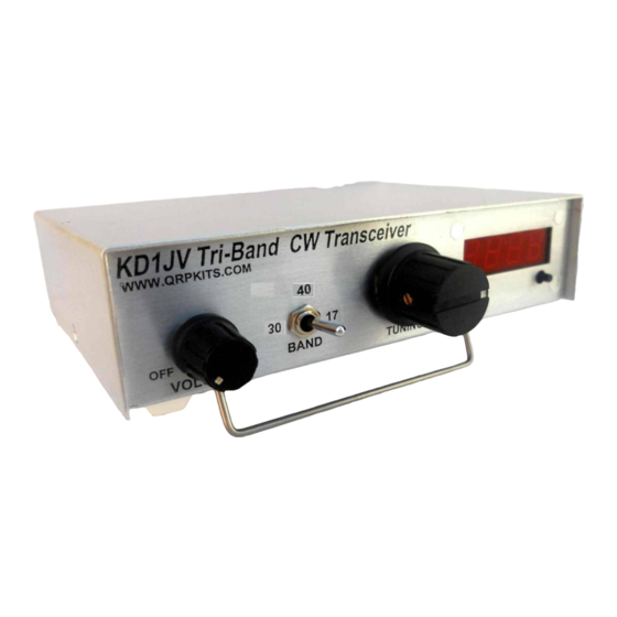
The KD1JV Tri-Bander CW transceiver
Table of Contents
Operation:................................................................2
Power on/off: .....................................................2
Band selection: ..................................................2
Tuning: ..............................................................2
Tuning Limits: ..............................................2
RIT:................................................................2
Keyer operation:.................................................2
Changing Keyer speed:..................................2
Message memories:.......................................2
Storing a message:.........................................3
To send a stored message:.............................3
Message pause and stop.................................3
Specifications:
Any three ham bands, 80, 60, 40, 30, 20, 17 or 15 meters - choose band mix at time of order.
●
5 watts output on all bands with 13.8V supply
●
Built in Iambic keyer with 5 to 40 wpm code speed, selectable Iambic A or B modes and two 63 character
●
message memories.
Receiver sensitivity, 0.2 uV MSD
●
DDS VFO for rock steady stability with 50 Hz and 200 Hz tuning rates
●
Easy to read four digit LED display with leading zero suppression.
●
Rotary knob tuning
●
RIT (receive incremental tuning)
●
Four IF crystals for excellent selectivity and opposite side band rejection
●
600 Hz audio filter
●
Audio derived AGC
●
Small size, 6" wide, 1.5" tall and 4" deep.
●
Light weight, 12 ounces.
●
Modest supply current requirements, 90 ma on receive (no signal) and 600 to 800 ma on transmit at 5W out
●
(current depends on band, higher bands draw more current)
Supply range : 13.8 V max, 8 V min.
●
1
Hendricks QRP kits
www.qrpkits.com
Straight key mode:.............................................3
Tune up mode:....................................................3
Speaker or headphones:......................................4
Circuit description:..................................................4
Microprocessor controller and DDS VFO:........4
Receiver: ............................................................4
Transmitter: .......................................................5
Parts List.................................................................6
Assembly Instructions:............................................7
Power up and test:.................................................18
Setting keyer Iambic A or B mode:...............3
Advertisement
Table of Contents

Related Manuals for QRPKits KD1JV


Summary of Contents for QRPKits KD1JV
-
Page 1: Table Of Contents
The KD1JV Tri-Bander CW transceiver Hendricks QRP kits www.qrpkits.com Table of Contents Operation:..............2 Setting keyer Iambic A or B mode:....3 Power on/off: .............2 Straight key mode:..........3 Band selection: ..........2 Tune up mode:............3 Tuning: ..............2 Speaker or headphones:........4 Tuning Limits: ..........2 Circuit description:..........4... -
Page 2: Operation
Operation: Power on/off: Power switch is part of volume control. Band selection: One of the three available bands are selected with a three position toggle switch (on-off-on). When a band is selected, the display will indicate the band in meters for a second. (80 for 80 meters, 40 for 40 ●... -
Page 3: Keyer Operation
60 Meter channel frequencies: Channel 1 : 5.3320 MHz USA only Channel 2 : 5.3480 MHz USA only Channel 3 : 5.3585 MHz USA only Channel 4 : 5.3730 MHz USA only Channel 5 : 5.4050 MHz International 60 Meters is a shard band with Homeland Security and other government agencies. There could be voice or digital mode operation on these channels and they have priority. -
Page 4: Straight Key Mode
Iambic mode. If A is currently enabled, B will be toggled on, the letter “B” will be annunciated and the display will show [b . ]. Conversely, if B is currently enabled, the letter “A” will be annunciated, the display will show [A .] for a second and then escape to normal operation. -
Page 5: Receiver
receive switching and produces the side tone. An Analog Devices AD9834 DDS chip is used for the VFO. Using a 60 MHz clock, direct frequency output to 21 MHz is possible. Receiver: The receiver is a classic SA612 circuit, widely used in QRP rigs. The 1 mixer input is double tuned for good image and out of band signal rejection. -
Page 6: Parts List
Parts List VALUE Markings/type VALUE Markings/type 10 ohms BRN/BLK/BLK/GLD BS-170 MOSFET TO-92 51 OHMS GRN/BRN/BLK/GLD J-171 P-channel j-fet TO-92 270 OHMS RED/VOL/BRN/GLD 2N3819 N-channel j-fet TO-92 470 OHMS YEL/VOL/BRN/GLD 2N3904 NPN TO-92 BRN/BLK/RED/GLD 2N7000 MOSFET TO-92 2.2 K RED/RED/RED/GLD FQPF27P06 P-CHN MOSFET TO-220F 7.5 K VOL/GRN/RED/GLD... -
Page 7: Assembly Instructions
If you loose, damage or are missing a part, send a message to parts@qrpkits.com for a replacement. Please specify the part type and value. For example, instead of saying you need R22, say you need a 1K resistor. - Page 8 Ink jet friendly diagram:...
- Page 10 Cabinet preparation: Before starting on the board assembly, the cabinet should be prepared first. This way, it will be ready to go when you finish building the board. Clean the cabinet. (optional) paint the cabinet. Apply decals. When labeling the band select switch, note that the center position should be the lowest frequency band. ●...
- Page 11 Part by part placement guide: Resistors pay attention to values highlighted as they can be easily confused with values with similar color coding. √ location Value Color code √ Location Value Color code 470 Ω YEL/VOL/BRN/GLD 270 Ω RED/VOL/BRN/GLD 51 Ω GRN/BRN/BLK/GLD BRN/BLK/RED/GLD 470 K...
- Page 12 U4 – 14 pin socket ● U6 – 28 pin socket ● Capacitors: There are four types of capacitors used. Some caps may have lead spacing too wide for the board holes. Please take a few minutes to “unkink” the formed ●...
- Page 13 Trimmer capacitor CT 7 – Green trimmer. Make sure the flat side of the part is facing the line drawn in the circle ● outline on the board. Transistors: Be sure to properly ready the part number on the three legged transistors so they go in the proper place. A magnifying glass maybe helpful for this.
- Page 14 Band specific parts: Part locations are listed in table for band A, then band B and then Band C. The lowest frequency band should be made band A and the highest frequency band C. For example, band A could be 80 meters, while band C would be 15 meters, but not the other way around. This ensures the highest frequency band has the shortest track lengths.
- Page 15 60 Meter value Type 150 pfd 151 mono C0G 680 pfd 681 mono C0G 1200 pfd 122 mono C0G 680 pfd 681 mono C0G 4.7 pfd 4.7 NPO Disk CT5/6 CT3/4 70 pfd Brown trimmer 20 turns #28 wire T37-2 Red 20 turns #28 wire T37-2 Red L5/6...
- Page 16 Board mounting into cabinet and wiring: (see photo next page) ● The band select switch and volume control are best wired to the board before it is installed into the case. ● Cut the hook up wire to the lengths listed in the table. Wires connecting to the on/off switch and volume control should be routed under the board.
- Page 17 Assembled board, wired into case: Note how wires “float” above the board.
-
Page 18: Power Up And Test
Power up and test: Wire up the power plug, center pin plus. Connect to power supply, plug into power jack on rig. Turn power on via volume control. Test for 5 volts between pins 8 and 3 of U1 or U2 (tests analog 5V reg, U5) and between pins 14 and 7 of U4 (tests digital 5V reg, U10). - Page 19 NOTE: When entering the Calibration mode, the default frequency values for reference and IF offset are loaded. ● This is done in case the values now stored in EEPROM become corrupted. Therefore, it is not possible to “test” the calibration by re-entering the calibration mode. If you wish to test the calibration, measure the transmit frequency on the highest band you have chosen to install into the rig, before and after calibration.
-
Page 20: Trouble Shooting Guide
Trouble shooting guide: In most cases, any problems with the getting the rig to work will be tracked down to soldering problems or miss placed parts. A close visual inspection of the board is often enough to find soldering problems or the miss-placed parts. Soldering problems fall into four groups: Missing solder connections Solder bridges between closely spaced pads which should not be connected togther. - Page 21 Schematics:...
Need help?
Do you have a question about the KD1JV and is the answer not in the manual?
Questions and answers