Table of Contents
Advertisement
Quick Links
Advertisement
Table of Contents
Troubleshooting

Related Manuals for Magnum Energy MagnaSine MS-PE Series


Summary of Contents for Magnum Energy MagnaSine MS-PE Series
- Page 1 MS-PE Series Pure Sine Wave Inverter/Charger Owner’s Manual...
- Page 2 The MS-PE Series inverter/charger may only be used in life support devices and systems with the express written approval of Magnum Energy. Failure of this inverter can reasonably be expected to cause failure of that life support device or system, or to affect the safety or effectiveness of that device or system.
- Page 3 • Use only copper wires with a minimum temperature rating of 90°C. • Listed or labeled equipment shall be installed and used in accordance with any instructions included in the listing or labeling. © 2013 Magnum Energy, Inc. Page ii...
- Page 4 CAUTION: This symbol indicates that failure to take a specifi ed action could result in damage to the equipment. Info: This symbol indicates information that emphasizes or supplements important points of the main text. Page iii © 2013 Magnum Energy, Inc.
-
Page 5: Table Of Contents
2.6.5 Neutral to Safety Ground Bonding ..............27 2.6.6 Disabling the Neutral-to-Ground Connection ...........28 2.6.7 Connecting a Large Ground Wire ..............28 Inverter Notifi cation Requirements ..............29 2.7.1 Inverter Warning Label ................29 Final Inspection ....................29 Functional Test ....................30 © 2013 Magnum Energy, Inc. Page iv... - Page 6 C-1 Appliance Power Consumption ................53 C-2 Inverter Output Waveforms ................53 Appendix D – Inverter/Charger Terminology ........54 Appendix E – Warranty and Service Information .........56 E-1 Limited Warranty .....................56 E-2 How to Receive Repair Service ................56 Page v © 2013 Magnum Energy, Inc.
- Page 7 Table 3-4, Remote Compatibility Level ................38 Table 4-1, Basic Troubleshooting (remote not available) ............43 Table A-1, AC Wiring Color Codes ...................47 Table A-2, DC Wiring Color Codes ................... 47 Table C-1, Typical Appliance Power Consumption ..............53 © 2013 Magnum Energy, Inc. Page vi...
-
Page 8: 1.0 Introduction
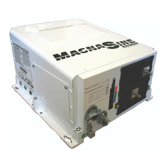
Introduction 1.0 Introduction Congratulations on your purchase of a MS-PE Series inverter/charger from Magnum Energy. The MS-PE Series is a “pure” sine wave inverter designed especially for rugged mobile applications, home backup power, and standalone applications that require 230 VAC/50 Hz power. Powerful, yet simple to use, this inverter/charger will provide you with years of trouble-free performance you have come to expect from Magnum Energy. -
Page 9: How An Inverter/Charger Works
Advanced Remote Control (ME-ARC50), Standard Remote Control (ME-RC50), Automatic Generator Start-Networked (ME-AGS-N), and Battery Monitor Kit (ME-BMK) can be used. See Section A-3 “Optional Equipment and Accessories” for more information on these products. © 2013 Magnum Energy, Inc. Page 2... -
Page 10: Features And Benefi Ts
Network Port (green label – RJ11 connection) Remote Port (blue label – RJ11 connection) Battery Temp Sensor Port (yellow label – RJ11 connection) Figure 1-1, Power Switch, Status LED, and Accessory Connection Ports Page 3 © 2013 Magnum Energy, Inc. -
Page 11: Figure 1-2, Electrical Connection Points
Mounting Flange – used to secure the inverter to a shelf or to a wall. Intake Air Vents (and on right side) Positive (+) DC Terminal Negative (-) AC Entry/Exit DC Terminal Connections Mounting Flange DC Equipment Ground Terminal Figure 1-2, Electrical Connection Points © 2013 Magnum Energy, Inc. Page 4... -
Page 12: Figure 1-3, Left Side Features
30 amps, or damage to the relays may occur. Model/Serial Number Label AC Access Cover Exhaust Air Vents (back side & right side rear) AC Input Circuit Breaker (CB1) Figure 1-3, Left Side Features Page 5 © 2013 Magnum Energy, Inc. -
Page 13: 2.0 Installation
If items appear to be missing or damaged, contact your authorized Magnum Energy dealer or Magnum Energy. If at all possible, keep your shipping box to help protect your inverter from damage if it ever needs to be returned for service. Save your proof-of-purchase as a record of your ownership;... -
Page 14: Figure 2-1, Simplifi Ed Installation Diagram - Single Inverter
POWER TO MS-PE INVERTER ERIES NVERTER HARGER HUNT ISCONNECT REAKER ME-BMK Battery Monitor with shunt (Magnum Accessory) ATTERY ME-SBC Smart Battery Combiner (Magnum Accessory) Figure 2-1, Simplifi ed Installation Diagram – Single Inverter Page 7 © 2013 Magnum Energy, Inc. -
Page 15: Locating The Inverter
Away from sensitive electronic equipment – High-powered inverters can generate levels of RFI (Radio Frequency Interference). Locate any electronic equipment susceptible to radio frequency and electromagnetic interference as far away from the inverter as possible. © 2013 Magnum Energy, Inc. Page 8... -
Page 16: Mounting The Inverter
IS MOUNTED IN THIS POSITION HOOD ( ON TOP ME-CB, EITHER THE MPX-CB, MS- CEFB, MMP-E MP-E ENCLOSURE ON BOTTOM MUST BE USED OUNTED TERMINALS TO THE RIGHT Figure 2-2, Approved Mounting Positions Page 9 © 2013 Magnum Energy, Inc. -
Page 17: Figure 2-3, Ms-Pe Series Dimensions And Side Reference
Installation Figure 2-3, MS-PE Series Dimensions and Side Reference © 2013 Magnum Energy, Inc. Page 10... -
Page 18: Wiring The Inverter - General Requirements
Ground wiring to and from the inverter 2.3.4 Torque Requirements • Torque all AC wiring connections to 1.8 N-m (16 in lbf). Torque DC cable connections from 13.6 to 16.3 N-m (10 to 12 ft lbf). Page 11 © 2013 Magnum Energy, Inc. -
Page 19: Dc Wiring
BLUE for negative (-); and GREEN (or GREEN w/YELLOW stripe) for DC ground to avoid polarity problems. Refer to Table A-2 (in Appendix A-3) for a list of equivalent DC wiring color codes for Europe and U.S./Canada. © 2013 Magnum Energy, Inc. Page 12... -
Page 20: Figure 2-4, Dc And Battery Temperature Sensor Wiring
Battery Bank’s Equipment Ground Wire Battery Bank’s Negative Cable Battery Bank’s Positive Cable DC System Grounding point [Electrode Conductor (i.e., ground busbar)] Battery Bank Figure 2-4, DC and Battery Temperature Sensor Wiring Page 13 © 2013 Magnum Energy, Inc. -
Page 21: Dc Wire Sizing
(#6 AWG) conductor if that is the only connection to the grounding electrode and that grounding electrode is a rod, pipe, or plate electrode. Note – May not allow continuous operation at full rated power. © 2013 Magnum Energy, Inc. Page 14... -
Page 22: Dc Cable Connections
(5/16 -18" bolt, placed between 5/8" length) the cable ring lug and battery the battery post. post battery cable (with ring lug) Figure 2-5, Battery Hardware Figure 2-6, Inverter DC Hardware Installation Installation Page 15 © 2013 Magnum Energy, Inc. -
Page 23: Wiring The Battery Bank
3. Connect the RJ11 connector end of the BTS cable to the yellow-labeled BTS port on the inverter (see Figure 1-1, Item 6). FRONT VIEW ~2.5 cm ~5.1 cm (~2") (~1") ~1.9 cm ¾") ~.95 cm diameter Cable (0.375") ~1.3 cm ½") SIDE VIEW Figure 2-7, Battery Temperature Sensor © 2013 Magnum Energy, Inc. Page 16... -
Page 24: Wiring The Inverter To The Battery Bank
If the batteries are in an enclosure, perform a fi nal check of the connections to the battery terminals, and then close and secure the battery enclosure. Page 17 © 2013 Magnum Energy, Inc. -
Page 25: Ac Wiring
80% of rating unless listed with a 100% continuous rating. Note² – Copper wire rated with 75°C insulation at an ambient temperature of 30°C (86°F). © 2013 Magnum Energy, Inc. Page 18... -
Page 26: Ac Terminal Block Connections
For multiple ground wires, use a pressure or mechanical connector to attach the single wire from the AC ground terminal to the input and output ground connections. HOT IN NEUT IN HOT OUT NEUT OUT GROUND (In & Out) Figure 2-8, AC Terminal Block Page 19 © 2013 Magnum Energy, Inc. -
Page 27: Ac Conductor Wiring
30A (single pole), and the minimum wire size is 5.3 mm /#10 AWG (In & Out). Refer to the wiring diagram in Figure 2-9. Note – AC Source is from either the utility/grid power (i.e., shorepower) or an AC generator. © 2013 Magnum Energy, Inc. Page 20... -
Page 28: Figure 2-9, Ac Wiring Input/Output
In mobile installations: Neutral is typically not connected to ground in main panel. .Maximum 30-amp breaker (single pole) required to inverter AC input Main Panel (Utility/Generator Input) Sub-Panel and Outlets (Inverter Loads) Figure 2-9, AC Wiring Input/Output Page 21 © 2013 Magnum Energy, Inc. -
Page 29: Grounding Inverters
Negative AC Ground DC Ground Grounding GEC-AC GEC-DC System Grounding Electrode Grounding Electrode Grounding Electrode (AC side dedicated) (AC and DC sides shared) (DC side dedicated) Figure 2-10, Grounding System for MS-PE Series © 2013 Magnum Energy, Inc. Page 22... -
Page 30: Sizing The Grounding Electrode Conductors
AC Ground DC Ground EGC - AC EGC - DC Grounding GEC-DC System GEC-AC Grounding Electrode Grounding Electrode (AC side dedicated) (DC side dedicated) Figure 2-11, Multiple Connections to DC Ground Rod (Method 1) Page 23 © 2013 Magnum Energy, Inc. -
Page 31: Figure 2-12, Multiple Connections To Dc Ground Rod (Method 2)
Neutral Negative Neutral Negative AC Ground DC Ground EGC - AC EGC - DC GEC-AC Grounding System GEC-DC Grounding Electrode (DC side dedicated) Figure 2-13, Single Connection to DC Ground Rod (Method 3) © 2013 Magnum Energy, Inc. Page 24... -
Page 32: System Bonding Jumper
3.3 mm (#12 AWG) 30-60 amps 5.3 mm (#10 AWG) 100 amps 8.4 mm (#8 AWG) 200 amps 13.3 mm (#6 AWG) 300 amps 21.1 mm (#4 AWG) 400 amps 26.7 mm (#3 AWG) Page 25 © 2013 Magnum Energy, Inc. -
Page 33: Grounding On Boats
On systems using an isolation transformer or a polarization transformer, the inverter neutral (and the transformer secondary neutral) may be grounded at the AC main grounding bus instead of at the inverter. © 2013 Magnum Energy, Inc. Page 26... -
Page 34: Neutral To Safety Ground Bonding
NEUT IN NEUT IN NEUT OUT NEUT OUT GROUND GROUND Neutral -to-Ground connection Neutral -to-Ground connection (inside AC compartment) (inside AC compartment) Figure 2-14, Neutral-to-Ground Figure 2-15, Neutral-to-Ground Connection (Inverter Mode) Connection (Standby Mode) Page 27 © 2013 Magnum Energy, Inc. -
Page 35: Disabling The Neutral-To-Ground Connection
Figure 2-17, Large Ground Wire nut [from 4 to 5 ft lbf (5.4 to 6.8 N-m)]. Connected to MS-PE Series Replace AC Access Cover plate and secure. © 2013 Magnum Energy, Inc. Page 28... -
Page 36: Inverter Notifi Cation Requirements
4. Replace the covers on the main electrical/distribution panel. 5. Replace the chassis access cover. 6. Verify the inverter’s front panel switch is in the OFF position. Info: If required by code, have the installation inspected by an electrical inspector. Page 29 © 2013 Magnum Energy, Inc. -
Page 37: Functional Test
If the inverter passes all the steps, the inverter is ready for use. If the inverter fails any of the steps, refer to the Troubleshooting section. AC Terminal Block blue AC Output brown 230 Vac brown (± 5%) blue Neutral to Ground < 0.5 Vac Figure 2-19, AC Voltage Checks © 2013 Magnum Energy, Inc. Page 30... -
Page 38: 3.0 Operation
AC HOT OUT Transfer Relay AC HOT IN CB1 (30A) AC NEUT OUT AC NEUT IN AC GROUND DC NEGATIVE DC POSITIVE FET Bridge Power Transformer Figure 3-1, Power Flow - Inverter Mode Page 31 © 2013 Magnum Energy, Inc. -
Page 39: Standby Mode
Figure 3-2, Power Flow - Standby Mode Battery Charging Magnum Energy’s MS-PE Series is equipped with an active PFC (Power Factor Corrected) and PI (Proportional-Integral) multi-stage battery charger. The PFC feature controls the amount of power used to charge the batteries in order to obtain a power factor as close as possible to 1 (or unity). -
Page 40: Figure 3-3, Automatic 4-Stage Charging Graph
Voltage Voltage Voltage Time Goes to Full Charge after Charge 4 hours in Rate Absorb Current Float Charge Time Monitored Constant Reduced No Current Current Current Current Figure 3-3, Automatic 4-Stage Charging Graph Page 33 © 2013 Magnum Energy, Inc. -
Page 41: Transfer Time
No Change No Change -0.15 -0.3V -0.6V -0.3 -0.6V -1.2V -0.45 -0.9V -1.8V -0.6 -1.2V -2.4V -0.75 -1.5V -3.0V 104F 113F 122F Temperature reading from BTS Figure 3-4, BTS Temperature to Charge Voltage Change © 2013 Magnum Energy, Inc. Page 34... -
Page 42: Protection Circuitry Operation
66.4 VDC LBCI 25.0 VDC 50.0 VDC LBCO* 20.0 VDC 40.0 VDC (1 minute delay) (18.0 – 24.4 VDC) (36.0 – 48.8 VDC) LBCO (immediate) 17.0 VDC 34.0 VDC *adjustable with remote control Page 35 © 2013 Magnum Energy, Inc. -
Page 43: Inverter Startup
On (solid) – Indicates Bulk Charging; the external AC input power is passing thru the inverter and powering the AC loads connected to the inverter’s output. Power ON/OFF pushbutton switch Charging/Inverting Status LED indicator Figure 3-5, Power Switch and Status Indicator © 2013 Magnum Energy, Inc. Page 36... -
Page 44: Factory Default Values
600 AmpHrs (Absorb Time = 120 minutes) Flooded – Liquid Lead Acid: Battery Type 24v = Absorb 29.2 VDC, Float 26.8 VDC 48v = Absorb 58.4 VDC, Float 53.6 VDC Charge Rate 100% VAC Dropout 150 VAC Page 37 © 2013 Magnum Energy, Inc. -
Page 45: Inverter Fan Operation
Older remote revisions will work with the MS-PE Series. However, to view the correct 230 VAC readings and settings, the following remote revisions are required. Table 3-4, Remote Compatibility Level Remote Models Revision Required ME-RC ≥ Revision 2.7 ME-ARC ≥ Revision 2.4 ME-RTR ≥ Revision 3.0 © 2013 Magnum Energy, Inc. Page 38... -
Page 46: 3.11 Parallel Operation
Each inverter must have appropriate AC and DC overcurrent protection. • All negative connections (i.e., inverter, battery) must be permanently connected to each other. No fuse or disconnect can be placed in the negative circuit. Page 39 © 2013 Magnum Energy, Inc. -
Page 47: Figure 3-6, Simplifi Ed Installation Diagram - Multiple Inverters (In Parallel)
(Magnum Accessory) GROU ATTERY BANK ME-BMK-NS DC Panel Battery Monitor (Part of Magnum Panel Series) (Magnum Accessory) Includes shunt & DC disconnects Figure 3-6, Simplifi ed Installation Diagram – Multiple Inverters (in parallel) © 2013 Magnum Energy, Inc. Page 40... -
Page 48: Parallel System Connections And Components
PTION AC LOADS AC SOURCE DC LOADS (Customer Connection) (Customer Connection) DC SOURCE (Customer Connection) (Customer Connection) Figure 3-7, Simplifi ed Magnum Panel Figure 3-8, Simplifi ed Magnum Panel (AC Panel) (DC Panel) Page 41 © 2013 Magnum Energy, Inc. -
Page 49: 4.0 Maintenance And Troubleshooting
Disable the AGS (if installed) when the boat or caravan is in a confi ned storage area. WARNING: If an AGS were to start and run the generator for an extended period of time in a confi ned area, a potentially fatal level of carbon monoxide (CO) could accumulate. © 2013 Magnum Energy, Inc. Page 42... -
Page 50: Troubleshooting
This is normal; see Section 3.5 (Battery Temperature DC charge voltage is (BTS) is installed, the DC voltage will Sensor Operation) for more information. higher or lower than increase or decrease depending on the expected. temperature around the BTS. Page 43 © 2013 Magnum Energy, Inc. -
Page 51: Resetting The Inverter
Info: If DC disconnects are not used, there may be a momentary spark when the positive battery cable is connected to the inverter’s terminal. This is normal and indicates that the inverter’s internal capacitors are being charged. © 2013 Magnum Energy, Inc. Page 44... -
Page 52: Appendix A - Specifi Cations And Optional Equipment
Shelf (top or bottom up) or wall Unit weight 24.5 kg (54 lb) Shipping weight 27.7 kg (61 lb) Max operating altitude 4570 m (15,000’) Specifi cations @ 25°C - Subject to change without notice. Page 45 © 2013 Magnum Energy, Inc. -
Page 53: A-2 Optional Equipment And Accessories
The CE Filter Box (PN: MS-CEFB) is an EMI fi lter designed to control conducted emissions on the AC and DC side of Magnum Energy MS-E and MS-PE Series inverters. It is used to ensure the stringent international standards for electromagnetic compatibility (EMC) are met. The MS-E and MS-PE Series inverters—when connected to the MS-CEFB—conform to CE Mark requirements for... -
Page 54: A-3 Wiring Color Codes For Europe And The U.s./Canada
Canada. In the U.S., the National Electrical Code (NEC) is the mandating authority; in Canada, it’s the Canadian Electrical Code (CEC). Most of Europe abides by the International Electrotechnical Commission’s (IEC) wiring color codes. The tables also list the labels that Magnum Energy applies to identify AC/DC wiring usage in its inverters. -
Page 55: Appendix B - Battery Information
AC utility or generator power. Info: For the MS-PE Series inverter/charger to perform optimally, a minimum battery bank of 200 AHr is recommended for moderate loads (<1000W) and greater than 400 AHr for heavy loads (≥1000W). © 2013 Magnum Energy, Inc. Page 48... -
Page 56: B-5 Battery Bank Sizing Worksheet
However, if the inverter is the primary AC source for the calculated load, the Total Amp- Hours should be multiplied by 1.2 to factor in an average 80% inverter effi ciency. Page 49 © 2013 Magnum Energy, Inc. -
Page 57: Battery Wiring Confi Gurations
= 200 AHr @ 12 VDC 6 VDC 6 VDC 200 AHr @ 6 VDC (200 AHr) (200 AHr) add voltage and capacity together add voltage add capacity in series in parallel Figure B-3, Series-Parallel Battery Wiring © 2013 Magnum Energy, Inc. Page 50... -
Page 58: Figure B-4, Battery Bank Wiring Examples (24-Volt)
(200 AHr) (200 AHr) (200 AHr) (200 AHr) 24-volt battery bank (two strings of four 6-volt batteries wired in series & connected in parallel) Figure B-4, Battery Bank Wiring Examples (24-volt) Page 51 © 2013 Magnum Energy, Inc. -
Page 59: Figure B-5, Battery Bank Wiring Examples (48-Volt)
12 VDC battery battery battery battery (100 AHrs) (100 AHrs) (100 AHrs) (100 AHrs) 48-volt battery bank (parallel two strings of four 12-volt batteries wired in series) Figure B-5, Battery Bank Wiring Examples (48-volt) © 2013 Magnum Energy, Inc. Page 52... -
Page 60: Appendix C - Power Consumption And Output Waveforms
It rises and falls smoothly with time. The grid puts out a sine waveform. Figure C-1, AC Waveforms Any plug-in AC equipment will operate from a sine wave inverter. Page 53 © 2013 Magnum Energy, Inc. -
Page 61: Appendix D - Inverter/Charger Terminology
Islanding - The condition present when the utility power grid fails and the inverter attempts to power the grid. An inverter which is “islanding protected” senses the loss of AC power from the grid and does not back feed into the grid system. © 2013 Magnum Energy, Inc. Page 54... - Page 62 Battery Temperature Sensor (BTS) automatically re-scales charge-voltage settings to compensate for ambient temperatures. Voltage – The pressure that causes electrical fl ow in a circuit. Watts – Measure of power output or utilization. Watts = Volts x Amps. © 2013 Magnum Energy, Inc. Page 55...
-
Page 63: Appendix E - Warranty And Service Information
Magnum Energy’s limit of liability under this warranty shall be the actual cash value of the product at the time the original purchaser returns the product for repair, determined by the price paid by the original purchaser. Magnum Energy shall not be liable for any other losses or damages. - Page 64 Magnum Energy, Inc. 2211 West Casino Rd. Everett, WA 98204 Phone: 425-353-8833 Fax: 425-353-8390 Web: www.magnumenergy.com PN: 64-0056 Rev A MS-PE Series Owner’s Manual...
Need help?
Do you have a question about the MagnaSine MS-PE Series and is the answer not in the manual?
Questions and answers