Table of Contents
Advertisement
Quick Links
Advertisement
Table of Contents

Related Manuals for Magnum Energy ME-SBC


Summary of Contents for Magnum Energy ME-SBC
- Page 1 ME-SBC Smart Battery Combiner Owner’s Manual...
- Page 2 Restrictions on Use The ME-SBC shall not be used in connection with life support systems, life saving or other medical equipment or devices. Use of the ME-SBC with this particular equipment is at your own risk. IMPORTANT PRODUCT SAFETY INSTRUCTIONS This manual contains important safety instructions that must be followed during the installation and operation of this product.
-
Page 3: Table Of Contents
List of Sections 1.0 Introduction ................1 2.0 Installation ................3 3.0 Adjusting the ME-SBC ............11 4.0 Limitations of Throughput ............. 12 5.0 LED Indicators ................ 13 6.0 Troubleshooting ..............14 7.0 Specifi cations ................. 15 8.0 Limited Warranty ..............16 List of Tables Table 2-4, Recommended Wires Sizes for 3% loss ...... -
Page 4: Introduction
Wide voltage range allows maximum charging fl exibility • Adjustable Voltage settings • Over-current shutdown • Front panel LED’s for status and troubleshooting • Reverse polarity protection • Virtually zero voltage loss • Bidirectional charging • Sense lead for long run applications ©2009 Magnum Energy Inc. -
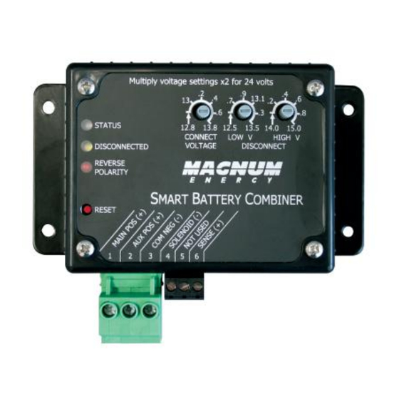
Page 5: Figure 1-1, Front Panel Interface
VOLTS DC and the LOW and HIGH VDC DISCONNECT settings for maximum charging fl exibility. 3. Reset Switch - Performs a full reset of the ME-SBC 4. Power Terminal Block- The oversized, removable terminal block allows fast and easy wire connections from the battery banks and makes provision for large wires to accomodate for long wire runs. -
Page 6: Installation
; using the supplied #8 x 3/4 screws (x4). Allow ample room to access the three adjustment dials, to view the LEDs and to access the terminal blocks; refer to Figure 2-1 for dimensions on the ME-SBC CAUTION: Do not mount the ME-SBC... -
Page 7: Figure 2-2, Power Terminal Block
2 Amps. The source that provides power to the solenoid must not exceed 40 VDC. This circuit switches DC Negative to the accessory terminal block position #4 entitled Solenoid (-). For this confi guration please see Figure 2-6. ©2009 Magnum Energy Inc. -
Page 8: Table 2-4, Recommended Wires Sizes For 3% Loss
After the initial self- test completes, the Status LED should be illuminated. If so, your ME-SBC is now ready for set-up; if not, please refer to the troubleshooting section. -
Page 9: Amp Combiner Mode
S m art B attery C o m b in er M ain A u xiliary (A U X) B attery B an k B attery B an k N e ga tiv e B us-ba r Figure 2-5, ME-SBC - 25 Amp Combiner Mode ©2009 Magnum Energy Inc. - Page 10 8. When all the connections are made and checked, plug the Power Terminal Block into the ME-SBC to supply DC power. 9. Immediately after applying DC power, the LED’s on the ME-SBC should come on as the unit goes through a power-up self-test. After the initial self- test completes, the Status LED should be Illuminated.
-
Page 11: Figure 2-6, Solenoid Drive
CHARG ER O N / O F F I NVERTER SHO RE AG S M ETER SETUP TECH ME-SBC Smart Battery Combiner Optional Solenoid Main Auxiliary (AUX) Battery Bank Battery Bank Negative Bus-bar Figure 2-6, Solenoid Drive ©2009 Magnum Energy Inc. - Page 12 Wiring - Remote Volt Sense The Remote Volt Sense Wire, or the wire connected to #6 - SENSE (+), can be used to better sense when the batteries are being charged. As the ME-SBC combines the Main and Auxiliary Batteries, the current path distributes...
-
Page 13: Figure 2-7, Remote Volt Sense
S m art B attery C o m b in er M ain A u xiliary (A u x) B attery B an k B attery B an k N e ga tiv e B us-ba r Figure 2-7, Remote Volt Sense ©2009 Magnum Energy Inc. -
Page 14: Adjusting The Me-Sbc
As long as the Main Battery voltage is between the Low Voltage Disconnect and the High Voltage Disconnect, and the Main bat- tery voltage is above the Connect Voltage, the ME-SBC will pass charging current through to the Auxiliary Battery. -
Page 15: Limitations Of Throughput
1/2 of the available amperage. It will continue to operate like this until the total available Amps safely drops to a level the ME-SBC can conduct con- tinuously. With a current probe, it may look like 50% of the rated output. -
Page 16: Led Indicators
Operation 5.0 LED Indicators The LEDs on the front of the ME-SBC are there to communicate the status of the ME-SBC , Faults, and Warnings. Use the table below to determine the status of the device. The Reverse Polarity LED indicates that the wiring to the Main Terminal is incorrect. -
Page 17: Troubleshooting
Auto Reconnecting capabilities. Wait for the charger to go into Float every 10 Sec Mode and check status again. If the ME-SBC still toggling it may be defective, otherwise it’s probably operating normally and protecting itself. Turn the knobs fully counterclockwise until they Adjustments are stop and then adjust up to the setting. -
Page 18: Specifi Cations
10 x 8 x 3 inches Unit Dimensions 4.2 x 5.4 x 1.4 inches Maximum Operating -40 to 185F (-40 to 85C) Temperature Maximum Storage -40 to 194F (-40 to 90C) Temperature Regulatory Ignition Protected Table 7-1, Specifications ©2009 Magnum Energy Inc. -
Page 19: Limited Warranty
3. During the limited warranty period, Magnum Energy will repair, or replace at Magnum Energy’s option, any defective parts, or any parts that will not properly operate for their intended use with factory new or rebuilt replacement items if such repair or replacement is needed because of product malfunction or failure during normal usage. - Page 20 Magnum Energy, Inc. 2211 West Casino Rd. Everett, WA 98204 Phone: 425.353.8833 Fax: 425.353.8390 Web: www.magnumenergy.com PN: 64-0019...
Need help?
Do you have a question about the ME-SBC and is the answer not in the manual?
Questions and answers