Advertisement
Table of Contents
- 1 Panel Descriptions
- 2 Top Panel
- 3 Mode Knob
- 4 Memory Button
- 5 MEMORY Indicator
- 6 On/Off Switch
- 7 MIDI Jacks
- 8 Basic Operation
- 9 Returning to the Factory Settings
- 10 Installing Batteries
- 11 Attaching the Rubber Feet
- 12 Main Specifications
- 13 Using the Unit Safely/Important Notes
- Download this manual
Advertisement
Table of Contents

Related Manuals for Boss Modulation MD-200


Summary of Contents for Boss Modulation MD-200
- Page 1 Owner’s Manual Before using this unit, carefully read “USING THE UNIT SAFELY” and “IMPORTANT NOTES” (the leaflet “USING THE UNIT SAFELY” and the Owner’s Manual (p. 19)). After reading, keep the document(s) where it will be available for immediate reference. ©...
-
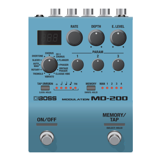
Page 2: Panel Descriptions
Panel Descriptions Top Panel Display Shows the parameters and the values. [RATE] knob Adjusts the speed at which the effect sound changes. Each time you press the button, the rate indication switches. Frequency # Tempo (BPM) Example indications 0.01 Hz = “0.01”, 1 Hz = “1.00”,... -
Page 3: Mode Knob
Selects the effect. ROTARY (ROT) rotary speaker. Mode Explanation Cyclically modulates a filter to AUTO WAH Chorus sound using cutting-edge BOSS (AWH) automatically create a wah effect. CHORUS (CHO) technology. Cyclically cuts the sound to create a SLICER CE-1 CHORUS A chorus sound that models the CE-1. - Page 4 Panel Descriptions Mode PARAM 1 PARAM 2 PARAM 3 (RESONANCE) (MANUAL) (LOW CUT FREQUENCY) Adjusts the amount of resonance Adjusts the center frequency at Cuts the frequency components FLANGER (feedback). which the effect is applied. below the specified frequency. (FLG) With the FLT (flat) setting, the low cut filter is not applied.
- Page 5 Panel Descriptions Mode PARAM 1 PARAM 2 PARAM 3 (TYPE) (WAVEFORM) (TONE) Cyclically modulates Selects the type of wave. Adjusts the tonal character. (TREMOLO): the volume. By alternately changing (PAN): the volume of left and right, this TREMOLO (TRM) produces the impression that the sound is moving between the left and right speakers when heard in stereo.
-
Page 6: Memory Button
Panel Descriptions [TAP DIVISION] button TAP DIVISION indicator Explanation ª ˇ ¸ ˙ Specifies the rate as a note value relative to the BPM. Eighth note (200%) Preventing accidental operation (panel lock) By long-pressing the [TAP DIVISION] button, you can Eighth-note triplet (300%) switch between enabling (unlocking) or disabling (locking) operation of the knobs and buttons. - Page 7 Panel Descriptions [MEMORY/TAP] switch Switches memories (p. 10). Long-press the [MEMORY/TAP] switch to select tap mode. By pressing the switch in time with the tempo of the song you're performing, you can specify a speed of modulation that matches the song. When the mode is ROTARY, this switches the rotation speed of the speaker.
- Page 8 Panel Descriptions Rear Panel When powering up (Connecting Your Equipment) Power-up equipment such as your guitar amp last. * To prevent malfunction and equipment failure, always turn down the When powering down volume, and turn off all the units before making any connections. Power-down equipment such as your guitar amp first.
-
Page 9: Midi Jacks
Panel Descriptions Side Panel Using the jack as EXP (Connecting Your Equipment) You can connect an expression pedal (sold separately: EV-30, Roland EV-5, etc.) and use it to control the rate or the volume of the effect sound (p. 13). * Use only the specified expression pedal. - Page 10 Saving and Switching Memories Saving to Memory Switching Memories Here’s how to save effect settings that you edited. Here’s how to recall a saved memory. Long-press the [MEMORY] button. Press the [MEMORY] button to select a memory. “Wrt.” The display indicates Each time you press the button, you cycle through Press the [MEMORY] button to select the save- the memories in the order of “MAN (manual) 0 1...
-
Page 11: Basic Operation
Overall Settings (Menu) Assigning functions to external pedals Basic Operation You can connect footswitches (sold separately: FS-5U, FS-6, FS-7) Press the [TAP DIVISION] button and to the CTL 1, 2/EXP jack, and use them to tap-input the rate or to switch memories. - Page 12 Overall Settings (Menu) Menu Parameter List Parameter Explanation Specify the functions of the [ON/OFF] switch, [MEMORY/TAP] switch, and MEMORY MEMORY About the mark MEMORY MEMORY footswitches connected to the CTL 1, 2/ (ON/OFF SWITCH EXP jack. FUNCTION) 5 Can be set and saved for each memory by the “Saving to Memory” (p. * The functions that can be assigned differ 10) operation.
- Page 13 Overall Settings (Menu) Parameter Explanation Parameter Explanation Specifies the function of an expression Selects the position at which the external pedal connected to the CTL 1, 2/EXP jack. effect unit is connected. No operation. The insert loop function is not used. oFF: OFF: The same operation as the...
- Page 14 Overall Settings (Menu) Parameter Explanation Parameter Explanation Specifies the function of E.LEVEL when Turns the insert loop function on/off. CHORUS or CE-1 CHORUS are selected as (INSERT LOOP SWITCH) OFF, ON the mode. If this is set to ELV (EFFECT LEVEL), the E.LEVEL knob adjusts the balance between (ON/OFF SWITCH FUNCTION the direct sound and the effect sound.
- Page 15 Overall Settings (Menu) Parameter Explanation Parameter Explanation Specifies whether program changes (RATE CC) are transmitted (on) or not transmitted (oFF). (DEPTH CC) Correspondence between memories (E.LEVEL CC) and program numbers (PC OUT) Memory Program number (PARAM1 CC) (PARAM2 CC) MEMORY 1–4 2–5 (PARAM3 CC) Specify the controller number...
- Page 16 Overall Settings (Menu) Parameter Explanation Specifies the source of realtime messages that are output to the MIDI OUT jack. Internal realtime messages (INTERNAL) are the source. (REALTIME SOURCE) Realtime messages from the (MIDI) MIDI IN jack are the source. Specifies whether MIDI messages received at the MIDI IN connector are retransmitted without change from the MIDI OUT (MIDI THRU)
-
Page 17: Returning To The Factory Settings
Appendix Returning to the Factory Settings Installing Batteries (Factory Reset) Here's how to return the MD-200 to its factory-set state. Insert the batteries as shown below, being careful to orient the batteries correctly. While holding down the [ON/OFF] switch and * Batteries should always be installed or [MEMORY/TAP] switch, turn on the power replaced before connecting any other... -
Page 18: Attaching The Rubber Feet
Appendix Attaching the Rubber Feet Main Specifications You can attach the rubber feet (included) if necessary. BOSS MD-200: Modulation Alkaline battery (AA, LR6) x 3, Attach them in the locations shown in the illustration. Power Supply AC adaptor (sold separately) * Using the unit without rubber feet may damage the floor. -
Page 19: Using The Unit Safely/Important Notes
USING THE UNIT SAFELY/IMPORTANT NOTES CAUTION Repairs and Data • Before sending the unit away for repairs, be sure to Keep small items out of the reach of children make a backup of the data stored within it; or you may prefer to write down the needed information. - Page 20 Licensed under the Apache License, Version 2.0 (the “License”); You may obtain a copy of the License at http://www.apache.org/licenses/LICENSE-2.0 • Roland, BOSS are either registered trademarks or trademarks of Roland Corporation in the United States and/or other countries. • Company names and product names appearing in this document are registered trademarks or trademarks of their respective owners.
Need help?
Do you have a question about the Modulation MD-200 and is the answer not in the manual?
Questions and answers