Table of Contents
Advertisement
Advertisement
Table of Contents

Related Manuals for DentalEZ CORE


Summary of Contents for DentalEZ CORE
- Page 1 CORE Delivery Unit Console Mount User Manual...
-
Page 2: Table Of Contents
Section II Preinstallation Utility Service Center ........41 Packaging ............9 Assistant’s Arm (Optional) ....... 41 Unit Placement ..........10 CORE Delivery Head ........42 Utility Service Center (USC) ......10 Touch Pads ............43 Section III Installation Console ............44 Console Adaptor Mount ........ - Page 3 CORE Console Mounted Unit www.DentalEZ.com 866-DTE-INFO PN: 2717-269C...
-
Page 4: Section I Introduction
(CMU). • For any questions about an order, please contact a DentalEZ Equipment customer The CORE CMU is intended to be used by trained service representative at 866-DTE-INFO. professional dental care personnel only, as an interface device to connect the dental operatory hand instruments to the appropriate supply utility such as air, water, vacuum, drain and electrical. -
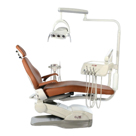
Page 5: Console Mounted Unit Features
Console Mounted Unit Console Mounted Unit Features Designed with simplicity in mind, the CORE product line provides a straightforward, easy-to-use delivery unit with common components, simple integrated holders and an easy-to-read pressure gauge. The console mounted unit positions StarDental® handpieces and ancillaries within easy, comfortable reach. -
Page 6: Dimensions
20¾" 15¼" 16" 23½" 27½" 7¾" 18" 4" 2" 22" 16" 57" 19" 21¾" 16¼" 15¾" 17½" 10½" to 23⅞" 6¼" 17½" Figure 2. Top and side view dimensions for the CORE console mounted delivery unit www.DentalEZ.com 866-DTE-INFO PN: 2717-269C... -
Page 7: Specifi Cations
• Atmospheric pressure range: 50 to 105 kPa • Reservoir capacity: 1.0 L Shipping (Package) Weight • CORE Traditional Delivery Head and Arms: 24.5 lb. (11.1 kg) • Magellan Delivery Unit Post: 13 lb. (5.8 kg) • Magellan Delivery Unit Support: 20 lb. (9 kg) •... -
Page 8: Classifi Cations
Section I Introduction DentalEZ Equipment ® Classifi cations Explanation of Symbols & Signs Medical-General Medical Equipment = Caution Certifi ed as to electrical shock, fi re and mechanical hazards only in = Warning E355890 53HN accordance with: ANSI/AAMI ES60601-1:2005 = Biohazard CAN/CSA C22.2 NO. -
Page 9: Safety Precautions
The antenna(s) used for this transmitter must not be co-located or operating in conjunction • Do not modify this equipment without with any other antenna or transmitter. permission from DentalEZ. Unauthorized modifi cation will void the warranty and could result in serious injury. If this NOTICE... - Page 10 Medical Device Safety standard IEC measures: 60601-1 may contribute to a reduced level • Reorient or relocate the receiving of safety of the CORE Delivery Unit. It is antenna. necessary for all accessory equipment and attachments to comply with IEC •...
- Page 11 CORE Console Mounted Unit www.DentalEZ.com 866-DTE-INFO PN: 2717-269C...
-
Page 12: Section Ii Preinstallation Packaging
® Packaging Unpacking Unit Cartons CAUTION The CORE CMU components are packaged and To avoid damage to the carton contents, do shipped according to the carton diagram shown not use a knife or sharp object to open the (Figure 3). -
Page 13: Unit Placement
Section II Preinstallation CORE Console Mounted Unit Unit Placement Utility Service Center (USC) Parts Included WARNING • Utility Service Center (USC) • DO NOT position equipment any place where it would interfere with unplugging • USC Cover the power cord from the receptacle. - Page 14 Section II Preinstallation DentalEZ Equipment ® Utility Service Center (USC) (Continued) Plumbing Contractor’s Procedure Chair Side Air Stop Valve WARNING Drain Fitting (Not • Before proceeding with plumbing Supplied) Water Stop Valve installation, comply with and maintain all applicable utility codes and regulations.
- Page 15 Section II Preinstallation CORE Console Mounted Unit Electrical Contractor’s Procedure The electrical contractor is to provide a covered 115V AC receptacle that meets all applicable utility codes and regulations (Figure 6). For the recommended location of the 115V AC receptacle, refer to the USC template.
-
Page 16: Section Iii Installation
Section III Installation DentalEZ Equipment ® Console Adaptor Mount CORE Chair Parts Included • Console Adaptor (Pinch Bolt/Washer Installed) Unit Support • Three Leveling Set Screws • M16 Bolt Figure 9. Position the unit support under the chair Pinch Bolt &... - Page 17 Section III Installation CORE Console Mounted Unit Console Adaptor Mount (Continued) NuSimplicity Chair of 1/2" fl at washers needed to provide a level condition across the two pads. Parts Included 4. Position the adaptor bar so that the three 1/2"...
-
Page 18: Console
Section III Installation DentalEZ Equipment ® Console Tools Required Service Console Covers • Torpedo Level 1. To remove the side covers, simply lift the covers until the magnets turn loose and take Installation the side covers off of the console. -
Page 19: Assistant's Arm (Optional)
Section III Installation CORE Console Mounted Unit Assistant’s Arm (Optional) Basic Fixed Asstistant’s Arm (Cuspidor Telescoping Arm Mounted) Carton Contents • High-volume Evacuator (HVE) Valve Handle • Saliva Ejector (SE) Valve Handle • Solids Collector Trap • Two Inline Connectors (For Syringe Connection) •... -
Page 20: Assistant's Instrumentation
Section III Installation DentalEZ Equipment ® Assistant’s Instrumentation Saliva Ejector (SE) Air/Water Syringe 1. Connect the SE valve to the 5/16" OD SE NOTE: The syringe for the delivery head is factory tubing (Figure 20). installed. 1. Pass the syringe tubing from the assistant’s... -
Page 21: Cuspidor (Optional)
Section III Installation CORE Console Mounted Unit Cuspidor (Optional) Simplicity until it contacts the pivot and adjust for desired rotation tension. Carton Contents 5. If reinstalling the bowl rinse spout is • Assistant’s Arm necessary, simply insert the bowl rinse spout into the hole closest to the bowl. -
Page 22: Delivery Head Arm Assembly
Section III Installation DentalEZ Equipment ® Delivery Head Arm Assembly Light Post (Optional) 1. Feed the low-voltage (black and white/blue NOTE: For complete light installation and gray) wire leads along with the colored instructions, refer to the manual supplied with tubing through the plastic grommet and then the light. -
Page 23: Fiber Optic Electrical (Optional)
Section III Installation CORE Console Mounted Unit Fiber Optic Electrical (Optional) Handpiece Tubing NOTE: The fi ber optic electrical wiring is factory NOTE: The handpiece tubing and optional fi ber installed. To complete installation, do the optic tubing is factory installed. -
Page 24: Finalizing Usc Installation
Section III Installation DentalEZ Equipment ® Finalizing USC Installation NOTE: The following instructions for fi nalizing Utility 9. Connect the 1/4" red tube, numbered 1, to the Service Center (USC) connections include optional city middle barb of the poppet valve in the USC. - Page 25 Section III Installation CORE Console Mounted Unit Finalizing USC Installation (Continued) *Water Regulator Vacuum Elbow Regulator Figure 26. Optional city water layout Figure 27. Typical installation Figure 28. Typical installation www.DentalEZ.com 866-DTE-INFO PN: 2717-269C...
-
Page 26: Power Module (Optional)
Section III Installation DentalEZ Equipment ® Power Module (Optional) 1. Unplug all cords from the receptacle in the 5. Pass the green wire of the main harness USC. through the umbilical and ground it to the power module, USC base or chair (Figure 30). - Page 27 CORE Console Mounted Unit www.DentalEZ.com 866-DTE-INFO PN: 2717-269C...
-
Page 28: Section Iv Testing
3. When fi nished, push the locking knob down. Tools Required Adjustable Arm • Phillips-head Screwdriver To check the maneuverability of the CORE adjustable arm, do the following: • 1/16" Hex Key 1. Depress and hold the brake release button. -
Page 29: Syringe
Section IV Testing CORE Console Mounted Unit Syringe Foot Control & Handpieces (Opt) Coolant Water Lines If the unit is equipped with a syringe, fi rst depress the air button and then the water button to test 1. At the foot control, fl ip the toggle to WET the fl ow. - Page 30 Section IV Testing DentalEZ Equipment ® Foot Control & Handpieces (Opt) (Continued) d. As the water is fl owing, continue the c. Hold the handpiece, fully depress the foot purging operation of the remaining tubings control, and observe the amount of air (moving from the left tubing to the right pressure delivered to the handpiece.
-
Page 31: Cuspidor
Section IV Testing CORE Console Mounted Unit Foot Control & Handpieces (Opt) Cuspidor (Optional) Flush Valve Check the cup fi ller and bowl rinse fl ow control valves for proper operation. 1. Remove the handpiece from its holder. Cup Fill 2. - Page 32 Section IV Testing DentalEZ Equipment ® Cuspidor (Optional) (Continued) Galaxy Cuspidor Bowl Rinse Check the cup fi ll and bowl rinse fl ow control 1. Depress and release the bowl rinse button on valves for proper operation. side of the cuspidor (Figure 40).
-
Page 33: Other Optional Features
Section IV Testing CORE Console Mounted Unit Other Optional Features Fiber Optics Follow the test procedures outlined in the instructions included in each fi ber optic handpiece package. Assistant’s Vacuum Accessories Evacuate one cup of water (8 oz. each) through the saliva ejector and the high-volume evacuator. -
Page 34: Section V Operation
Section V Operation DentalEZ Equipment ® Delivery Head Delivery Head Positioning WARNING The horizontal and vertical location of the delivery • To prevent possible injury due to head can be varied by doing the following: accidental operation, do not leave young children unattended. -
Page 35: Syringe
Section V Operation CORE Console Mounted Unit Syringe Foot Control The syringe is designed to deliver air or water, or a The speed of the handpiece is controlled by mixture of air and water, as required. depressing the disc located on the foot control (Figure 44). -
Page 36: Assistant's Vacuum Accessories
Section V Operation DentalEZ Equipment ® Assistant’s Vacuum Accessories Clean Water System Operation of the clean water system is as follows: WARNING • Flip the toggle switch to the ON position (Figure Do not hang objects weighing more than 46). -
Page 37: Cuspidor
Section V Operation CORE Console Mounted Unit Cuspidor (Optional) Cuspidor design features: • Cuspidor pivots, allowing easier patient access. • The bowl rinse operates automatically using the adjustable timing feature. • Both the cup fi ll and bowl rinse spouts are removable for sterilization. -
Page 38: Section Vi Care
To clean the solids collector located at the Do not use abrasive cleaning agents. instrument end of the assistant’s arm, do the following: The CORE delivery unit should be cleaned as 1. Push the lever on the saliva ejector upward to follows: equalize pressure. -
Page 39: Disinfecting
CORE Console Mounted Unit Disinfecting CAUTION • Use extreme caution when selecting the proper chemical disinfectant for the CORE delivery unit. • Avoid using disinfectants in spray containers because they may cause premature staining, discoloration and/or damage to the unit. -
Page 40: Section Vii User Service Information Troubleshooting
DentalEZ Equipment ® Troubleshooting WARNING A full color, fold-out tubing diagram of the CORE CMU is provided with this manual. • Before servicing, always disconnect the external power by unplugging the unit The following charts should be used when from the power receptacle. - Page 41 Section VII User Service Information CORE Console Mounted Unit Troubleshooting (Continued) Handpiece Symptom Possible Cause(s) Solution No drive air Drive air fl ow adjustments on pinch valves Turn adjustments screw counterclockwise to adjust drive air pressure. are closed Set to manufacturer’s recommended pressure.
- Page 42 Section VII User Service Information DentalEZ Equipment ® Troubleshooting (Continued) Arm System Symptom Possible Cause(s) Solution Horizontal arms Unit is not properly leveled Verify unit is level. Also, verify arms are properly seated. Adjust drift left or right tension or set screws as needed.
-
Page 43: Service Instruction
• Non-Salvage Components Figure 48. Model/serial number on CORE delivery head All other material unsuitable for recycling should be disposed of properly. For specifi c questions regarding material type, contact DentalEZ customer service. -
Page 44: Utility Service Center
Section VIII Parts Lists/Diagrams DentalEZ Equipment ® Utility Service Center Assistant’s Arm (Optional) Part/Kit Name Part/Kit No. Part/Kit Name Part/Kit No. Water Actuator Valve 3801-637 14 Holder 3802-305 Stop Valve 3800-960 Air Regulator 3801-638 Air Regulator Gauge Repl. Kit, Watts 3802-266 Water Regulator Gauge Repl. -
Page 45: Core Delivery Head
Section VIII Parts Lists/Diagrams CORE Console Mounted Unit CORE Delivery Head Part/Kit Name Part/Kit No. 1 CORE Rigid Arm Cap 3802-553 2 CORE Flex Arm Cap 3802-554 3 CORE Flex Arm Cover 3802-555 4 Master ON/OFF Toggle 3802-063 5 Flush Toggle... -
Page 46: Touch Pads
13 CORE HP Holder w/ Valve 3802-546 14 CORE HP Blank 3802-547 15 CORE Unit Cover 3802-548 16 CORE Unit Water Adjustment Valve 3802-549 17 CORE Head to Flex Arm Cap 3802-551 18 CORE Head to Flex Arm Key 3802-552 www.DentalEZ.com 866-DTE-INFO PN: 2717-269C... -
Page 47: Console
Section VIII Parts Lists/Diagrams CORE Console Mounted Unit Console Part/Kit Name Part/Kit No. Plug 3802-212 Side Covers 3802-220 Top Covers 3802-221 Air Valve Assembly 3801-584 5** Solid Trap 3625-338 Solids Collector Cap 3802-011 Hole Plug 3802-007 O-Ring 3801-720 Pressure Regulator... -
Page 48: Simplicity Cuspidor (Optional)
Section VIII Parts Lists/Diagrams DentalEZ Equipment ® Simplicity Cuspidor (Optional) Part/Kit Name Part/Kit No. Strainer 3801-205 Cup Fill Spout 3802-003 Bowl Rinse Spout 3802-010 Cover 3802-413 5a Cup Fill Valve, 3-Way 3802-199 5b Bowl Rinse Valve, 2-Way 3802-200 Actuator Valve... -
Page 49: Galaxy Cuspidor (Optional)
Section VIII Parts Lists/Diagrams CORE Console Mounted Unit Galaxy Cuspidor (Optional) Part/Kit Name Part/Kit No. Push Button Valve 3802-348 Cuspidor Bowl 3802-406 Drain Strainer 3802-407 Bowl Rinse Spout 3802-408 Cup Fill Spout 3802-409 Flow Control Valve 3802-410 Air Control 3802-411 www.DentalEZ.com... -
Page 50: Foot Control
Section VIII Parts Lists/Diagrams DentalEZ Equipment ® Foot Control Air/Water Syringe Part/Kit Name Part/Kit No. Part/Kit Name Part/Kit No. Drive Air Repair Kit 3802-417 Cartridges 3802-203 Wet/Dry Toggle Valve 3802-418 Syringe Tip Kit 3802-205 Chip Air Valve 3802-419 O-Rings (Complete Set) -
Page 51: Hve Nozzle
Part/Kit Name Part/Kit No. HVE Repair Kit 3802-154 SE Repair Kit 3802-153 Full Replacement Parts Kit 3801-927 Full Replacement Parts Kit 3801-926 DentalEZ Parts Online To order parts online, visit www.dentalezparts.com or scan QR code with smartphone. www.DentalEZ.com 866-DTE-INFO PN: 2717-269C... -
Page 52: Emc Information
Guidance and Manufacturer’s Declaration – Electromagnetic Emissions The CORE CMU is intended for use in the electromagnetic environment specifi ed below. The customer or the user of the CORE CMU should assure that it is used in such an environment. - Page 53 Guidance and Manufacturer’s Declaration – Electromagnetic Emissions The CORE CMU is intended for use in the electromagnetic environment specifi ed below. The customer or the user of the CORE CMU should assure that it is used in such an environment.
-
Page 54: Limited Warranty
CORE Console Mounted Unit DentalEZ and its employees are proud of the products we provide in the dental community. We stand behind these products with a warranty against defects in material and workmanship as provided below. In the event you experience diff iculty with the application or operation of any of our products, please contact our Technical Service Department at our expense at 866-DTE-INFO (866-383-4636). - Page 55 2500 Highway 31 South Bay Minette, Alabama 36507 866-DTE-INFO www.dentalez.com © DentalEZ® Alabama, Inc. Printed in USA PN: 2717-267C May, 2019...
Need help?
Do you have a question about the CORE and is the answer not in the manual?
Questions and answers