Advertisement
Quick Links
Warranty:
BYOC, Inc. guarantees that your kit will be complete and that all parts and components
will arrive as described, functioning and free of defect. Soldering, clipping, cutting,
stripping, or using any of the components in any way voids this guarantee. BYOC, Inc.
guarantees that the instructions for your kit will be free of any majors errors that would
cause you to permanently damage any components in your kit, but does not guarantee
that the instructions will be free of typos or minor errors. BYOC, Inc. does not warranty
the completed pedal as a whole functioning unit, nor do we warranty any of the
individual parts once they have been used. If you have a component that is used, but feel
it was defective prior to you using it, we reserve the right to determine whether or not the
component was faulty upon arrival. Please direct all warranty issues to:
sales@buildyourownclone.com This would include any missing parts issues.
Return:
BYOC, Inc. accepts returns and exchanges on all products for any reason, as long as they
are unused. We do not accept partial kit returns. Returns and exchanges are for the full
purchase price less the cost of shipping and/or any promotional pricing. Return shipping
is the customer's responsibility. This responsibility not only includes the cost of
shipping, but accountability of deliver as well. Please contact
sales@buildyourownclone.com to receive a return authorization before mailing.
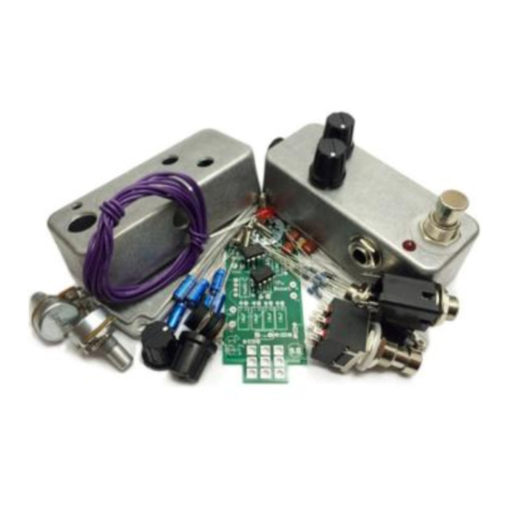
Build Your Own Clone
27V Boost
Kit Instructions
Advertisement

Subscribe to Our Youtube Channel
Related Manuals for BYOC 27V Boost


Summary of Contents for BYOC 27V Boost
- Page 1 BYOC, Inc. does not warranty the completed pedal as a whole functioning unit, nor do we warranty any of the individual parts once they have been used.
- Page 2 That being said, we will do our best to help you as much as we can. Our philosophy at BYOC is that we will help you only as much as you are willing to help yourself. We have a wonderful and friendly DIY discussion forum with an entire section devoted to the technical support and modifications of BYOC kits.
-
Page 3: Table Of Contents
27V Boost Kit Instruction Index Parts Checklist……………………………………….page 4 Populating the Circuit Board……………………….page 6 Enclosure Hardware Assembly…………..………...page 11 Wiring………………………………………………..page 16 Operation Overview………………………………...page 20 Schematic……………………………………………page 21... -
Page 4: Parts Checklist
Parts Checklist for the 27V Boost Kit Resistors: Metal Film (5-band) Carbon (4-band) 1 – 1k/102 (Brown/Black/Black/Brown/Brown) (Brown/Black/Red/Gold) 1 – 2k2/222 (Red/Red/Black/Brown/Brown) (Red/Red/Red/Gold) 1 - 4k7/472 (Yellow/Purple/Black/Brown/Brown) (Yellow/Purple/Red/Gold) 5 - 10k/103 (Brown/Black/Black/Red/Brown) (Brown/Black/Orange/Gold) 1 - 18k/183 (Brown/Gray/Black/Red/Brown) (Brown/Gray/Orange/Gold) 1 - 100k/104 (Brown/Black/Black/Orange/Brown) (Brown/Black/Yellow/Gold) 1 –... - Page 5 Hardware: 1 - predrilled enclosure w/ 4 screws 1 – 27V Boost circuit board 1 - 3pdt footswitch 1 - LED 1 – External nut AC Jack 2 – Enclosed Audio Jacks 4 - rubber bumpers 2 - lock washers (for in and out jacks)
-
Page 6: Populating The Circuit Board
Populating the Circuit Board Step 1: Add all the resistors. Resistors are not polarized and can be inserted in either direction. - Page 7 Step 2: Add the diodes. Be sure to match the end of the diodes with the stripe to the layout on the PCB. The striped end should go in the square solder pad.
- Page 8 Step 3: Add the ICs. Be sure to orient them correctly. There may be a "U" shaped notch on the IC between pins 1 and 8. Line that up with the screenprint on the PCB. If your IC does not have a notch, look for a dot to indicate pin Pin one on the PCB will be a square hole.
- Page 9 Step 4: Add the film and ceramic disc capacitors. These are non-polarized and can go in either direction. The ceramic disc capacitor is highlighted in yellow.
- Page 10 Step 5: Add the aluminum electrolytic capacitors. These ARE polarized, meaning there is a positive and negative end. The positive side will have a longer lead and goes in the square solder pad. The negative side will have a shorter lead and a stripe running along the body of the cap, and goes in the round solder pad.
-
Page 11: Enclosure Hardware Assembly
Enclosure Hardware Assembly Step 1: Mount the DC adapter jack. - Page 12 Step 2: Mount the potentiometers. You will mount them opposite each other, so that when looking into the enclosure, the right potentiometer will have its lugs facing towards the ac jack, and the left potentiometer will have its lugs facing the audio jacks.
- Page 13 Step 3: Mount the Audio Jacks. You want to orient them so that the SLEEVE terminals (beveled corner of the jack) are facing away from each other. If looking at the inside of the enclosure, the OUTPUT jack will have its sleeve terminal facing towards the AC jack.
- Page 14 Step 4: Remove both nuts from the footswitch and mount the footswitch. Orient the footswitch so that the flat sides of the solder lugs are like the diagram below. NOTE: There are no actual number markings on the footswitch. There are two correct ways you can orient the footswitch.
- Page 15 FOOT SWITCH SOLDER LUG DESIGNATIONS...
-
Page 16: Wiring
Wiring FLIP PCB OVER!!! STEP 1: Wire the PCB as shown in the diagram below. Make all connections to the back side of the PCB and solder on the top (screen printed) side of the PCB. Make the wires as short as possible but allow enough length so that if you need to do any trouble shooting later, you will be able to do so without having to remove all the enclosure mounted components. - Page 17 Step 2: Once the AC jack, potentiometers, and IN/OUT jacks are wired, insert the LED in its hole. Insert the long lead into the square hole!!! might want to slightly bend the leads away from each other to keep them in the holes for now.
- Page 18 Step 3: Flip the PCB right-side-up, tuck the wires into the enclosure, and place the PCB onto the footswitch. DO NOT SOLDER YET!!!!! It is extremely important that when you place the PCB on the footswitch, you make sure to tuck all the wires out of the way so that that PCB can rest flush against the enclosed jacks and footswitch.
- Page 19 Step 4: Solder ONLY 1 of the footswitch lugs. Your PCB should be recessed inside the enclosure about 1cm. It should be level. Some of your components may be sticking up out of the enclosure just a bit, particularly the film capacitors. This is to be expected. This is OK. The lid has a deep recess.
-
Page 20: Operation Overview
Operating Overview VOL: Adjusts the overall output volume. TREB: Cuts or boosts frequencies over 2.2KHz. Clockwise boosts. Counter Clockwise cuts. Noon on the dial is flat EQ response. Power supply: 2.1mm negative tip. Current Draw: 15mA Input Impedance: 3.3 Meg ohms Output Impedance: 50k ohms... - Page 22 Please visit http://byocelectronics.com/board For any technical support Copyright 2015 BYOC, Inc.
Need help?
Do you have a question about the 27V Boost and is the answer not in the manual?
Questions and answers