Burkert 8225 Operating Instructions Manual
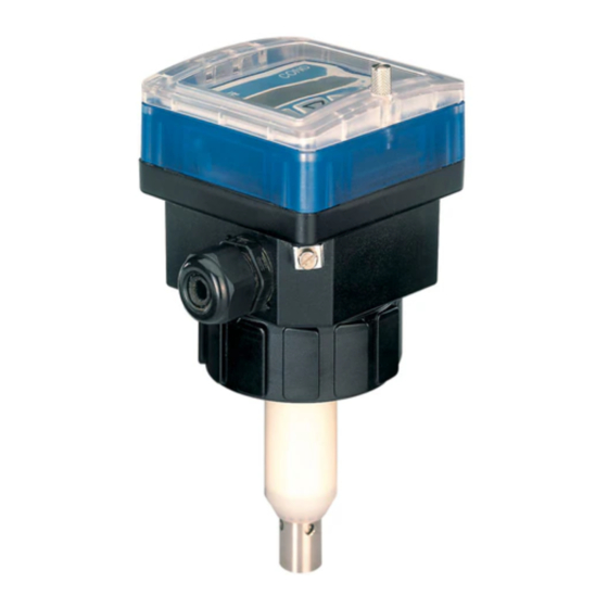
Digital conductivity transmitter
Hide thumbs
Also See for 8225:
- Manual (42 pages) ,
- Mechanical assembly (4 pages) ,
- Instruction manual (85 pages)
Table of Contents
Advertisement
TABLE OF CONTENTS
1
INTRODUCTION ............................................................................................... E-2
1.1
Unpacking and Control ...................................................................................... E-2
1.2
About this Manual .............................................................................................. E-2
1.3
User's Responsibility for Safety ........................................................................ E-2
1.4
Electromagnetic compatibility ............................................................................ E-2
2
SPECIFICATION ............................................................................................... E-3
2.1
Type Specification ............................................................................................. E-3
2.2
Design and Measuring Principle ....................................................................... E-5
2.3
Dimensions ........................................................................................................ E-6
2.4
Technical Data ................................................................................................... E-7
2.5
Measuring range electrodes .............................................................................. E-8
3
INSTALLATION ................................................................................................ E-9
3.1
Installation Guidelines ....................................................................................... E-9
3.2
Installation .......................................................................................................... E-9
3.3
General Electrical Connection ......................................................................... E-10
3.4
Electrical Wiring ............................................................................................... E-10
3.4.1 8225 without relays ................................................................................ E-10
3.4.2 8225 with Relays .................................................................................... E-12
3.4.2 8225 with 230/115 VAC Power Supply .................................................. E-13
4
OPERATING ................................................................................................... E-14
4.1
Operating and Control Elements ..................................................................... E-14
4.2
Operation Mode Display .................................................................................. E-15
4.3
Calibration Mode Display ................................................................................ E-16
4.3.1 Languages .............................................................................................. E-16
4.3.2 Engineering Units ................................................................................... E-17
4.3.3 Cell Constant .......................................................................................... E-17
4.3.4 Temperature Compensation Coefficient ................................................ E-17
4.3.5 Output Current ........................................................................................ E-19
4.3.6 Relay ....................................................................................................... E-19
4.3.7 Filter Function ......................................................................................... E-21
4.4
Test Menu ........................................................................................................ E-21
4.4.1 Offset-Compensation ............................................................................. E-21
4.4.2 Span-Compensation ............................................................................... E-22
4.4.3 Display of non-compensated Conductivity ............................................. E-22
4.4.4 Conductivity Simulation .......................................................................... E-22
5
MAINTENANCE .............................................................................................. E-23
5.1
Storing and Cleaning of the Electrode ............................................................ E-23
5.2
Trouble-shooting Guide ................................................................................... E-23
5.3
Factory Settings of the 8225 ........................................................................... E-23
5.4
Spare Parts List ............................................................................................... E-24
APPENDIX ........................................................................................................ G-1
Examples of connections for transmitter 8225 .................................................. G-1
CONDUCTIVITY 8225
E-1-
Ref. 425552
Fluid Control Systems
Advertisement
Table of Contents

Subscribe to Our Youtube Channel
Related Manuals for Burkert 8225


Summary of Contents for Burkert 8225
-
Page 1: Table Of Contents
General Electrical Connection ................. E-10 Electrical Wiring ....................E-10 3.4.1 8225 without relays ................E-10 3.4.2 8225 with Relays ..................E-12 3.4.2 8225 with 230/115 VAC Power Supply ..........E-13 OPERATING ....................E-14 Operating and Control Elements ..............E-14 Operation Mode Display .................. E-15 Calibration Mode Display ................ -
Page 2: Introduction
-1 8225 Digital Conductivity Transmitter -1 Operating Instruction Manual If this symbol appears, it indicates To ensure that you have recieved the... -
Page 3: Type Specification
2 SPECIFICATION CONDUCTIVITY 8225 2.1 Type Specification 2.1.2 Transmitter 8225 with 12-30 VDC power supply ° Conductivity transmitter Gasket Sensor Cable entry Ident N STANDARD TYPES WORLWIDE 8225 with 4-20 mA K=0,01 DIN 43650 PG9 418950 8225 with 4-20 mA... - Page 4 2 SPECIFICATION CONDUCTIVITY 8225 2.1.2 Transmitter 8225 with 115/230 VAC power supply ° Conductivity transwithter Gasket Sensor Cable entry Ident N STANDARD TYPES WORLWIDE 8225 with 4-20 mA K=0,01 2XPG 13,5 426935 8225 with 4-20 mA K=0,1 2XPG 13,5 426936...
-
Page 5: Design And Measuring Principle
2 SPECIFICATION CONDUCTIVITY 8225 2.2 Design and Measuring Principle Measuring Principle Design Conductivity is defined as the ability of a The compact conductivity transmitter solution to conduct electrical current. The combines a sensor and a transducer with load carriers are ions (e.g. dissolved salts display in a splash-proof plastic IP65 or acids). -
Page 6: Dimensions
2 SPECIFICATION CONDUCTIVITY 8225 2.3 Dimensions Version: "WORLDWIDE" See part 2.1 1/2" G 1/2" G Version: "NORTH AMERICA" See part 2.1 E-6- Fluid Control Systems... -
Page 7: Technical Data
2 SPECIFICATION CONDUCTIVITY 8225 2.4 Technical Data Pressure class PN 6 0 to 100 °C (32 to 212 °F) (*) Fluid temperature 0 to 60 °C (32 to 140 °F) Ambient temperature 0 to 60 °C (32 to 140 °F) - Page 8 2 SPECIFICATION CONDUCTIVITY 8225 2.5 Measuring range of electrodes K = 0.1 und K = 0.01 K = 1.0 K = 10 The conductivity transmitter can be fitted with 4 different electrodes with cell constants 0.01; 0.1; 1.0 and 10. The electrode is selected according to the measuring range and medium by using the table below.
-
Page 9: Installation
3 INSTALLATION CONDUCTIVITY 8225 3.2 Installation 3.1 Installation Guidelines The conductivity transmitter 8225 can be Pressure-Temperature Diagram easily installed into pipes using our specially Please be aware of the pressure- designed fitting system. (S020/1500) temperature dependence according to the respective fitting material. -
Page 10: Installation
CONDUCTIVITY 8225 3.3 General Electrical Connection 3.4 Electrical Wiring 12-30 VDC The connecting cable conducts the 3.4.1 8225 without relays measuring signal and power supply and must not be installed in combination with Electrical wiring either via cable plug to DIN high voltage or high frequency lines. - Page 11 3 INSTALLATION CONDUCTIVITY 8225 Connection to PG 13.5 cable gland Remove the cover, pull the cable though PG 13.5 cable gland and wire according to pin assignment cf. fig. 3.4. 1: Not assigned 2: L+ (12-30 VDC) 3: L- 4: Earth (earth lug)
- Page 12 3 INSTALLATION CONDUCTIVITY 8225 3.4.2 Connection 8225 with relays Strap The electrical wiring is possible via 2 cable glands. Remove the cover, pull the cable through 1 2 3 4 PG 13.5 and wire according to Switch assignment cf. fig. 3.6).
-
Page 13: 8225 With Relays
230 VAC 115 VAC 115 VAC 1 2 3 4 1 2 3 4 Switch. Strap (cf. fig. 3.7) Strap Sensor connection Sensor connection 9 10 Fig. 3.8 Electrical wiring 8225 with power supply 230/115 VAC E-13- Fluid Control Systems... -
Page 14: Operating And Control Elements
4 OPERATION CONDUCTIVITY 8225 The operation is divided into 3 main menus 1 Display Conductivity, temperature and output current are displayed within this menu, and the "HOLD" function can also be obtained. 2 Parameter Definition All the necessary adjustments, such as language, engineering units, cell constant, temperature compensation factor, 4-20 mA measuring range, relay and filter are set within this menu. -
Page 15: Operation Mode Display
4 OPERATION CONDUCTIVITY 8225 4.2 Operation Mode Display The following units are indicated within the operation mode display: Conductivity in the required engineering unit. If "0000" or "9999" 12.6 m S is displayed, input value is to low, respectively to high, change unit or decimal point position Temperature in °C or °F. -
Page 16: Calibration Mode Display
4 OPERATION CONDUCTIVITY 8225 ENTER 4.3 Calibration Mode: Press simultaneously for 5 seconds The following adjustments are set in the calibration mode display: Selection between English, German, French or Italian. LANGUAGE UNIT Selection of engineering units for conductivity and temperature. -
Page 17: Engineering Units
ELEC CST ENTER measuring range. This can be adjusted depending on the application as follows: K-new = (Cond. reference / Cond. 8225) x K-real. 0..9 The reference conductivity can be given either by a buffer solution or reference device. T ° COEFF ENTER If K=00.0000, the device is blocked and the displayed... - Page 18 4 OPERATION CONDUCTIVITY 8225 After, the device will be immersed into the solution (temperature < T- or < 25 °C if T- > 25 °C) and the solution is heated up. The temperature compensation coefficients will automatically be determined until T+ or 25 °C (if T+ < 25 °C) is reached. The values are memorized and can be called up any time by selecting "SPECIAL"...
-
Page 19: Output Current
4 OPERATION CONDUCTIVITY 8225 4.3.5 Output Current Within this mode, the measuring range of the conductivity measuring range is entered, which corresponds to the output current 4-20 mA. E.g. 0 to 10 mS/cm corresponds to 4- 20 mA. The beginning of the measuring range might be larger than the end of it, e.g. 0 to 10 mS/cm corresponds to 20-4 mA (inverted output signal). - Page 20 4 OPERATION CONDUCTIVITY 8225 RELAY 1- = 00.00 ENTER Enter the lowest value of threshold 1 0..9 1- = 01.50 1 += 00.00 ENTER Enter the highest 0..9 value of threshold 1 INV NO 1 += 02.50 ENTER INV YES DEL.1 = 000...
-
Page 21: Filter Function
4 OPERATION CONDUCTIVITY 8225 4.3.7 Filter Function The damping set within this sub-menu prevents display and output current fluctuations. There are 10 steps available. However, the first step ("FILTER 0") has no damping function. FILTER FILTER 0 ENTER 0..9 FILTER 9... -
Page 22: Span-Compensation
4 OPERATION CONDUCTIVITY 8225 4.4.2 Span-Compensation Within this mode, the user can change the basic setting of 20 mA. The procedure is identical to the Offset-compensation. The transmitter generates 20 mA, if the Enter key is pressed when "OFFSET" is displayed. If the displayed value is incorrect, it can be corrected by entering the measured value. -
Page 23: Maintenance
By pressing the ENTER key, the user can access the main menu although the device works with the factory settings (see § 5.3). The transmitter will need recalibrating. If this message appears persistently, please return the device to the factory. 5.3 Factory-settings of 8225 at Delivery Language: English Relay: 00.00... -
Page 24: Spare Parts List
5 MAINTENANCE CONDUCTIVITY 8225 5.4 Spare Parts List Position Specification Order-No. Complete sensor housing with plug connector, ring and union nut 425524 Sensor housing for one PG with ring and union nut 425525 Sensor housing for 2 PG with ring and union nut... - Page 25 5 MAINTENANCE CONDUCTIVITY 8225 Fig. 5.1 Spare Parts Explosion Drawing E-25- Fluid Control Systems...
- Page 26 CONDUCTIVITY 8225 E-26- Fluid Control Systems...
- Page 27 Vanne de régulation avec positionneur 1067 Beispiel - Example - Exemple: LINK - 1067 Leitfähigkeit Transmitter 8225 Kompakt 12/30VDC ohne Relais Connection Conductivity transmitter 8225 compact 12/30 VDC without relay Connexion transmetteur de conductivité 8225 compact 12-30 VCC sans relais G-1- Fluid Control Systems...
- Page 28 Vanne de régulation avec positionneur 1067 Beispiel - Example - Exemple: LINK - 1067 Leitfähigkeit Transmitter 8225 Kompakt 12/30VDC mit Relais Connection Conductivity transmitter 8225 compact 12/30 VDC with relays Connexion transmetteur de conductivité 8225 compact 12-30 VCC avec relais G-2- Fluid Control Systems...
- Page 29 Electrovanne de régulation avec régulateur PI 8624 Beispiel - Example - Exemple: LINK - 8624 Leitfähigkeit Transmitter 8225 Kompakt 12/30VDC ohne Relais Connection Conductivity transmitter 8225 compact 12/30 VDC without relay Connexion transmetteur de conductivité 8225 compact 12-30 VCC sans relais G-3- Fluid Control Systems...
- Page 30 Electrovanne de régulation avec régulateur PI 8624 Beispiel - Example - Exemple: LINK - 8624 Leitfähigkeit Transmitter 8225 Kompakt 12/30VDC mit Relais Connection Conductivity transmitter 8225 compact 12/30 VDC with relays Connexion transmetteur de conductivité 8225 compact 12-30 VCC avec relais G-4- Fluid Control Systems...
- Page 31 SERVICE Australia Burkert Fluid Control Systems Bürkert Contromatic Niederlassung Dresden Unit 1 No.2, Welder Road China/HK Ltd. Christian Bürkert Straße 2 Seven Hills NSW 2147 Guangzhou Representative Office D-01900 Großröhrsdorf Tel +61 (0) 2 967 461 66 Rm. 1305, Tower 2...
- Page 32 Tel +48 (0) 22 840 60 10 Turkey Fax +48 (0) 22 840 60 11 Bürkert Contromatik Akiskan Kontrol Sistemleri Ticaret Singapore Burkert Contromatic Singapore Pte.Ltd. 1203/8 Sok. No. 2-E No.11 Playfair Road Yenisehir Singapore 367986 Izmir Tel +65 383 26 12...
Need help?
Do you have a question about the 8225 and is the answer not in the manual?
Questions and answers