Advertisement
Quick Links
Performance Specifications ........................................ 2
Notes ......................................................................... 2
Rear Panel .................................................................. 3
Section Location ........................................................ 4
Block Diagram ...................................................... 5 - 7
Interconnection Diagram .................................... 8 - 10
Main Schematic and PCB ................................. 11 - 16
Control Schematic and PCB ............................. 17 - 20
Balanced Schematic and PCB ........................... 21 - 22
Volume/Tone Schematic and PCB ..................... 23 - 26
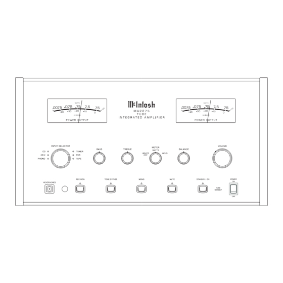
INTEGRATED AMPLIFIER
CONTENTS
SERVICE MANUAL
TUBE
Data Schematic and PCB ................................... 27 - 28
Pushbutton Schematic and PCB ........................ 29 - 30
Amplifier Schematic and PCB ............................ 31 - 34
Power Supply Schematic and PCB ..................... 35 - 38
Meter Schematic and PCB ................................. 39 - 40
Backup PS Schematic and PCB ................................ 41
Terminal Schematic and PCB ................................... 42
Parts List ............................................................ 43 - 48
Exploded View and Parts List ............................. 49 - 52
Repacking Instructions ............................................. 53
Advertisement

Subscribe to Our Youtube Channel
Summary of Contents for McIntosh MA-2275-2
-
Page 1: Table Of Contents
TUBE INTEGRATED AMPLIFIER CONTENTS Performance Specifications ........2 Data Schematic and PCB ........27 - 28 Notes ................. 2 Pushbutton Schematic and PCB ......29 - 30 Rear Panel ..............3 Amplifier Schematic and PCB ......31 - 34 Section Location ............4 Power Supply Schematic and PCB ..... -
Page 2: Performance Specifications
PERFORMANCE SPECIFICATIONS Power Output Preamplifier Maximum Voltage Output Minimum sine wave continuous average power output per Phono: 8V channel, both channels operating is: High Level: 8V 75 watts into a 2 ohm load Main Out: 8V at preamp output 75 watts into a 4 ohm load 75 watts into an 8 ohm load Voltage Gain High Level to Tape output: 0dB... - Page 3 MA2275 TOP AND REAR VIEWS OUTPUTS INPUTS POWER AMP IN PREAMP TAPE TAPE TUNER CD 2 PHONO CAUTION RISK OF ELECTR C SHOCK DO NOT OPEN CAUTION AVIS MA2275 FOR CONT NUED PROTECT ON RISQUE DE CHOC ELECTR QUE - NE PAS CD INPUT AGA NST FIRE HAZARD REPLACE ONLY WITH SAME OUVRIR REMPLACER PAR UN FUS BLE DE MEME...
-
Page 4: Section Location
SECTION LOCATIONS TOP VIEW WITH COVERS REMOVED POWER TRANSFORMER OUTPUT OUTPUT TRANSFORMER TRANSFORMER VOLUME/TONE METER PUSHBUTTON CONTROL DATA BALANCED TERMINAL TERMINAL MAIN POWER SUPPLY BACKUP POWER SUPPLY PCB CHOKE FILTER BOTTOM VIEW WITH COVER REMOVED... -
Page 5: Block Diagram
MA2275 BLOCK DIAGRAM... - Page 6 INTERCONNECT...
- Page 7 MA2275 MAIN 049965 SH 1 OF 2...
- Page 8 MAIN 049965 SH 2 OF 2 129472 Rev. A TUNER TAPE TAPE OUT 2 OUT 1 AMP IN...
- Page 9 MA2275 CONTROL 049966...
- Page 10 CONTROL 049966 129473 Rev.A DS12 DS11 DS13 DS10 ASSY1 DS15...
- Page 11 MA2275 BALANCED 049967...
- Page 12 VOLUME/TONE VOLUME/TONE 049968 049968...
- Page 13 MA2275 VOLUME/TONE 049968 129475 Rev.A...
- Page 14 DATA 049969 Rev.A 129476...
- Page 15 MA2275 PUSHBUTTON 049970 STANDBY/ 5.6V J1:18 J1:1 5.6V MUTE J1:17 J1:2 5.6V MONO J1:16 J1:3 TONE STANDBY/ON MUTE MONO 5.6V J1:15 BYPASS J1:4 5.6V J1:14 REC MON J1:5 J1:13 J1:6 J1:12 MUTE TONE BYPASS REC MON J1:7 J1:11 MONO J1:8 J1:10 TONE J1:9...
- Page 16 AMPLIFIER 049971...
- Page 17 MA2275 AMPLIFIER 049971 129478 Rev.A...
- Page 18 POWER SUPPLY 049972 485V 485V 485V 300V REGULATOR 490V J16:1 -400V 300V -400V J7:1 AMP MUTE J16:2 AMP MUTE J7:2 TURN ON J16:3 TURN/ON J7:3 J16:4 FIL A FIL A J7:4 J16:5 FILGND J7:5 47uF AMP MUTE -400V J16:6 FIL B FIL B J7:6 POWER AMPLIFIER...
- Page 19 MA2275 POWER SUPPLY 049972 RED BLU 129526 Rev.A Q6 Q3 GRN/BLK...
- Page 20 METER 049973...
- Page 21 MA2275 BACKUP PS TERMINAL 050007 050052 TERMINAL 050052...
-
Page 22: Parts List
CAP MONO .1uF 50V 20% Z5U 061305 RELAY REED FORM 1A 5V 500 OHMS 087050 RES MF 22.1K 1% 1/4W 144187 TUBE 12AX7A MCINTOSH 165065 CAP MONO .1uF 50V 20% Z5U 061305 RELAY REED FORM 1A 5V 500 OHMS 087050... - Page 23 MA2275 PARTS LIST con’t LED GREEN 5MM HI-INTENSITY 058165 RELAY REED FORM 1A 5V 500 OHMS 087050 IC DC MOTOR DRIVER 133191 SENSOR IR 38KHZ 121046 LED GREEN 5MM HI-INTENSITY 058165 RES NETWORK 2X220K ISO 144262 RES MF 324 OHM 1% 1/4W 144338 LED GREEN 5MM HI-INTENSITY 058165...
- Page 24 PARTS LIST con’t RES MF 332k 1% .5W 144355 RES MO 18K 5% 1W 144286 RES MF 22.1K 1% 1/4W 144187 RELAY POWER TV5 12V 087070 RES MF 2.74K 1% 1/4W 144304 RES MO 100K 5% 2W 144438 RES MF 22.1K 1% 1/4W 144187 TRANSISTOR NPN 132223...
-
Page 25: Exploded View And Parts List
MA2275 EXPLODED VIEW and PARTS LIST (4X) (4X) (4X) (6X) (4X) (6X) (4X) (4X) (4X) (6X) (3X) (3X) (4X) (4X) (4X) (4X) (4X) (6X) (4X) (4X) (11X) (3X) (3X) (9X) (3X) (4X) (5X) (4X) (4X) (6X) (6X) (3X) (4X) (4X) (3X) (8X) (6X) - Page 26 AIR PIPE 017921 LOGO/SELECTOR BACKLIGHT 100292 SCREW MACH 6-32 X 3/8 PH FH BLK 017901 LOGO/ PUSHBUTTON BACKLIGHT 165069 TUBE KT88 MCINTOSH 017907 TITLE/PUSHBUTTON BACKLIGHT 165065 TUBE 12AX7A MCINTOSH 094431 TAPE FOAM WHT 3/8W X 1/32 THK 165067 TUBE 12AT7...
-
Page 27: Repacking Instructions
MA2275 REPACKING INSTRUCTIONS... - Page 28 SERVICE MANUAL The continuous improvement of its products is the policy of McIntosh Laboratory Incorporated, who reserve the right to improve design without notice. Because of the constant upgrading of McIntosh products’ circuitry and components, the Company cannot insure, and does not warrant, the accuracy of the within schematic material, which is intended for information only.


Need help?
Do you have a question about the MA-2275-2 and is the answer not in the manual?
Questions and answers