
Related Manuals for McIntosh MA8900


Summary of Contents for McIntosh MA8900
-
Page 1: Integrated Amplifier
McIntosh Laboratory, Inc. 2 Chambers Street Binghamton, New York 13903-2699 Phone: 607-723-3512 www.mcintoshlabs.com MA8900 Integrated Amplifier Owner’s Manual... -
Page 2: Table Of Contents
Customer Service Front Panel Displays, Controls, Your decision to own this McIntosh MA8900 Inte- If it is determined that your McIntosh product is in Push-buttons and Jack ............16 grated Amplifier ranks you at the very top among need of repair, you can return it to your Dealer. You Setup Mode: discriminating music listeners. -
Page 3: General Information
MA8900. go to www.mcintoshlabs.com. trol, Trigger and Passthru Outputs. 2. Apply AC Power to the MA8900 and other McIn- 8. The IR Input, with a 1/8 inch mini phone jack, is Data Port Connectors tosh Component(s) only after all the system compo-... -
Page 4: Introduction
Amplifier. The Power Amplifier section of the ing. There is a Balanced Input for connection of a A Power Control connection for convenient Turn-On MA8900, with a power output of 200 watts per chan- source component. of McIntosh Power Amplifiers, Source Components nel, will drive a pair of quality Loudspeakers to a high and Accessories is included. -
Page 5: Dimensions
Dimensions Dimensions The following dimensions can assist in determining the best location for your MA8900. There is additional information on the next page pertaining to installing the MA8900 into cabinets. Front View of the MA8900 " 44.5cm " " 18.1cm Side View of the MA8900 19.4cm... -
Page 6: Installation
Installation Installation The MA8900 can be placed upright on a table or " 1/16 shelf, standing on its four feet. It also can be custom 43.34cm installed in a piece of furniture or cabinet of your choice. The four feet may be removed from the bottom... -
Page 7: Connections
MA8900 Rear Panel Connections Rear Panel Connections The identification of Rear Panel Connections for the MA8900 Integrated Amplifier is located on a separate folded sheet contained in the Owner’s Manual Packet. Refer to separate sheet “Mc1A” for the Rear Panel Connections. -
Page 8: Connecting Components
2. Connect a Control Cable from the McIntosh Turn- mation, note 8” for additional information. Notes: 1. If the MA8900 is part of a Home Theater System, proceed to “PassThru” connection on table Power Control Out Jack to the Digital Audio Audio Connections: page 9. -
Page 9: Passthru Connections
Passthru Connections Passthru Connections The MA8900 can be part of a Multichannel Sound System for BLU-RAY-Audio, DVD-Audio and Home Theater Movies. The Right and Left Front Channels from an Audio/Video Control Center can “Passthru” A/V Processor the MA8900. In the following example the UNBAL- ANCED 6 Input will become the “Passthru”... -
Page 10: Connecting For Bi-Amplification
The MA8900 Power Amplifier, together with an ad- ditional separate Power Amplifier, may be used to Bi-Amplify a Loudspeaker System. In the illustration on this page, the Power Amplifier of the MA8900 is connected to the Midrange/High Frequency Section of the Loudspeaker. The additional separate Power Amplifier is connected to the Low Frequency Section of the Loudspeaker System. -
Page 11: How To Connect Loudspeakers
Banana Plugs are for use in the United States and When connecting the Loudspeaker Hookup Cables to The McIntosh MA8900 Power Amplifier Circuitry the MA8900 Amplifier Output Terminals please fol- is designed for Loudspeakers with an impedance of Canada only: low the steps below: 2 ohms, 4 ohms or 8 ohms. -
Page 12: Connecting Loudspeakers
Connecting Loudspeakers 5. Connect the MA8900 power cord to an active AC outlet. Spade Lug or Wire Connections: 6. Connect the Loudspeaker hookup cables to the MA8900 Negative Output Terminal and Posi- tive Output Terminal indentified as 2Ω (ohms), 4Ω (ohms) or 8Ω (ohms) connection to match the impedance of the Loudspeaker, being careful to observe the correct polarities. -
Page 14: Remote Control Push-Buttons
Intosh Models displaying choices on a video Radio Program (were applicable) screen EXIT the TRIM Menu and is used with McIntosh Activates the TRIM Mode. GUIDE is Models displaying information or choices on a video used with McIntosh Models displaying... -
Page 15: How To Use The Remote Control
McIntosh Source Components connected to the MA8900 via the Data Ports. Notes: 1. If at any time the MA8900 seems unrespon- sive to the HR085 Remote Control Commands, press the DEVICE Push-button to select first. -
Page 16: Front Panel Displays, Controls, Push-Buttons And Jack
Connection for low impedance EQUALIZER Push-button with STANDBY/ON Push-button with indica- dynamic headphones, for private indicator, when deactivated the tor switches the MA8900 ON or OFF listening audio signal bypasses the Equal- (Standby) and resets the microprocessors izer Controls OUTPUT 1 and 2 Push-buttons with... -
Page 17: Setup Mode
1. Press and hold in the INPUT Control to enter the The first Firmware Number is for the Main Circuitry PUT)”. Refer to figure 3. SETUP MODE. Refer to figure 2. of the MA8900 and can be identified at any time by... - Page 18 “B” to “M”. Refer to figure 10. to figure 5. connected (refer to page 8, step 13). RENAME: BAL The MA8900 Default Input Names (UNBAL 1, BAL, SETUP: UNBAL 4 >MAL < COAX 1, etc.) as indicated on the Front Panel Dis-...
-
Page 19: Output Settings
19. Rotate the INPUT Control until the “_” empty SETUP: OUTPUT 2 space to the right of character I is flashing, then how the MA8900 Output 1, Output 2 and Headphones Switched function. rotate the VOLUME (ADJUST) Control to change Figure 22 the “_”... -
Page 20: Power Control Triggers 1 And 2
Power Control Triggers 1 and 2 Data Ports By default the Power Control TRIGger 1 and TRIGger Data Port Connections between the MA8900 and a SETUP: TRIGGER 2 2 are assigned to activate when Output 1 or Output 2 McIntosh Source Component allow for basic function Output 2 is selected. -
Page 21: Passthru
Remote Control Codes The MA8900 may be remotely controlled from other The HR085 Remote Control included with the When the MA8900 is part of a Home Theater or equipment connected to the Rear Panel RS232 Jack. MA8900 utilizes the NORMAL McIntosh Control... -
Page 22: Ir Sensor
Power Mode Factory Reset The MA8900 Front Panel Sensor, which receives The MA8900 incorporates an Auto Off Feature, which If it becomes desirable to reset all the adjustable set- the signals from the HR085 Remote Control, can be automatically places the preamplifier into the Power... -
Page 23: Microprocessor Reset
Reset of the Microprocesors Reset of the Microprocesors Reset of Microprocessors In the unlikely event the controls of the MA8900 stop functioning, the microprocessors can be reset by per- forming the following: 1. Press the STANDBY/ON Push-button until the STANDBY/ON LED Indicator switches Off. -
Page 24: How To Operate The Ma8900
COAX 1 The Red LED above the STANDBY/ON Push-button ed), Mono/Stereo, Display Bright- 48kHz lights to indicate the MA8900 is in Standby mode. ness, Meter Backlight and HXD To switch ON the MA8900, Press the STANDBY/ON Mode (when Headphones are... -
Page 25: Equalizer Mode
Source Components can have slightly different volume 1. Select the MC Phono Source Input. returns to indicate the Source Selection and Volume levels resulting in the need to readjust the MA8900 2. Select TRIM “PHONO RESISTANCE, 400Ω” as Level. To verify the Balance setting without changing Volume Control when switching between different indicated on the Front Panel Information Display. -
Page 26: Mono/Stereo Mode
Refer to figure 63. METER LIGHTS INFORMATION DISPLAY ILLUMINATION MONO / STEREO The Brightness Level of the MA8900 Front Panel In- ______ Figure 65 formation Display can be adjusted from bright to dim Figure 63 by performing the following: 1. -
Page 27: Headphone Hxd
Guard Indicators will momentarily illuminate during Equalizer COAX 1 MUTE peaks in the audio signals. In the event the MA8900 Press the Front Panel EQUALIZER Push-button to 48kHz over heats, due to improper ventilation, high ambient activate the MA8900 Equalizer Control Circuitry for... -
Page 28: How To Make A Recording
Refer to the MA8900 Output Connection Diagrams the Front Panel OUTPUT 2 Push-button or press on amplifier with a MA8900. The first way is to use the located on the separate folded sheet “Mc2B” and the Remote Control, the BLUE (Setup) Push-button separate amplifier instead of the MA8900 built-in figure 74. -
Page 29: Equalizer Controls
Optical and Coaxial Digital Inputs B TRUMPET When a Digital Input (Optical or Coaxial Connection) FRENCH HORN IN F on the MA8900 is selected, the Front Panel Display TENOR TROMBONE BRASS will indicate the sample rate when a signal is present BASS TROMBONE IN F “48kHz”. -
Page 30: Usb Input Operation With A Computer
How to Operate the MA8900, con’t USB Input Operation and Driver Installation Requirements: 1. A PC Computer with a functioning The MA8900 USB Input provides the capability to USB Port. playback music from a computer, when the computer 2. Windows 7 (SP1 or greater), is connected to the rear panel USB connector. -
Page 31: How To Operate The Ma8900
McIntosh MA8900 USB When the USB Input is selected on the McIntosh el Click on the “McIntosh Icon” (located in the Win- Input. An example of just one of the available applica- MA8900, the Front Panel Display indicates the dows notification area on the right side of the taskbar) tions is “JRiver Media Center”. -
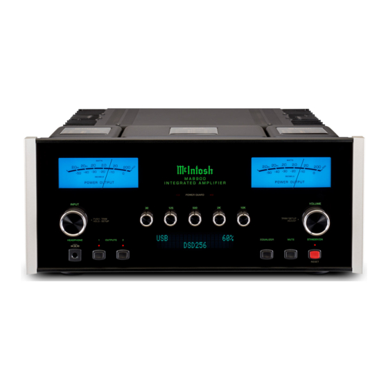
Page 32: Photo
Photo... -
Page 33: Amplifier Specifications
MA8900 Amplifier Specifications Amplifier Specifications Power Output Sensitivity (for rated output) Maximum Input Signal 200 watts is the minimum sine wave continuous aver- High Level, 250mV unbalanced, 500mV balanced High Level, 8V unbalanced, 16V balanced age power output per channel, both channels operating Phono MM, 2.5mV... - Page 34 240 Volts, 50/60Hz at 2.25 amps (PCM) DSD64, DSD128, DSD256, Standby: Less than 0.25 watt DXD352.8kHz, DXD384kHz Note: Refer to the rear panel of the MA8900 for the cor- rect voltage. Digital Inputs Overall Dimensions Coaxial: 0.5V p-p/75 ohms Width is 17-1/2 inches (44.45cm) Optical: -15dbm to -21dbm (TOS Link) Height is 7-5/8 inches (19.37cm) including feet...
-
Page 35: Packing Instructions
#10 flat washer 1-3/4 inch needed, please call or write Customer Service Depart- 017937 Plastic foot ment of McIntosh Laboratory. Refer to page 2. Please 400159 #10-32 x 3/4 machine screw see the Part List for the correct part numbers. - Page 36 McIntosh Laboratory, Inc. 2 Chambers Street Binghamton, NY 13903 www.mcintoshlabs.com The continuous improvement of its products is the policy of McIntosh Laboratory Incorporated who reserve the right to improve design without notice. Printed in the U.S.A. McIntosh Part No. 04174700...
Need help?
Do you have a question about the MA8900 and is the answer not in the manual?
Questions and answers