Table of Contents
Advertisement
Advertisement
Table of Contents

Related Manuals for Tenmars ST-140


Summary of Contents for Tenmars ST-140
- Page 1 Vibrómetro (acc/vel/desplazamiento), salida USB Tenmars TN-ST140D...
- Page 2 ST-140 Vibration Meter ST-140D Datalogging Vibration Meter User’s Manual HB2ST1400001...
-
Page 3: Table Of Contents
CONTENTS Introduction ............1 Accessories............1 Safety Precaution..........1 Meter Description ..........2 Operation ............3 5.1 Turn ON backlight 5.2 Datalogging Single Sata Entry Manually: 5.3 Reading Record Data In Memory: 5.4 Data Hold And Maximum Read Value: 5.5 Auto Power Off: 5.6 Accelerometer Installation: 5.7 Function Settings: Step 1~Step 6 Software Installation ........ -
Page 4: Introduction
ST-140/ST-140D Introduction This meter measures the vibrations of the rotating and reciprocating machines, as well as bearing damage, measurement items are acceleration, speed, displacement, which can check if the machine is to be repaired or upgrade. Accessories Meter User manual... -
Page 5: Meter Description
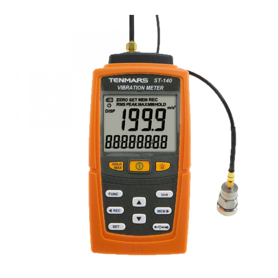
ST-140/ST-140D 4 Meter Description Accelerometer input terminal LED work light. LCD display screen Maximum hold and data hold button Power switch button Backlight button Function selection button Left button/REC record button Settings function button 10. Down button 11. Confirm button/LED work light control button 12. -
Page 6: Operation
ST-140/ST-140D 5 Operation Connect the accelerometer with the magnetic base and lock one side of the cable; connect the other end of the cable with the accelerometer input terminal of the meter, and then attach the accelerometer to the test object. -
Page 7: Turn On Backlight
ST-140/ST-140D 5.1 Turn ON backlight Under power ON status, press the button to turn ON the backlight, and then press the button again to turn OFF the backlight function directly. *The backlight will automatically turn OFF after being lit for 15seconds. -
Page 8: Accelerometer Installation
ST-140/ST-140D 5.6 Accelerometer Installation: When a permanent measuring point needs to be created on a machine but you do not want to drill holes on the machine, bonding studs can be used. These studs can be fixed on the measuring point using hard adhesives; we recommend... - Page 9 ST-140/ST-140D Put on the sensor with the magnetic base to the measuring point like shown in below by gently rolling it over the edges. Avoid magnet breakdown.
-
Page 10: Function Settings: Step 1~Step
ST-140/ST-140D 5.7 Function Settings: Step 1~Step 6 Press the button for over 2 seconds to enter the Step1~Step 7 settings. STEP 1. Setting date and time: Entering date and time setting mode. Press the button to select the item to change;... - Page 11 ST-140/ST-140D STEP 3. Setting automatic record time: Set whether to enable automatic record time mode; now OFF or ON will start flashing on the LCD. Then press the buttons to change whether to turn the automatic record mode ON or OFF.
- Page 12 ST-140/ST-140D STEP 5. Clear all recorded memory data (ALL): 1. Steps 4 and 5 will not appear if there is no recorded data, and it will skip directly to Step 7. 2. Enter clear all memory record data mode (ALL); now the number of data entries will be displayed on the LCD and ALL will start flashing.
-
Page 13: Software Installation
ST-140/ST-140D 6 Software Installation Supported operating systems: XP/Windows7/Windows 8.1/Windows10 Downloading PL-2303 execution software: Place the CD included with this meter into the CD/DVD-ROM drive of the PC to connect to and install the desktop program: Execute the PC desktop software program: ... -
Page 14: General Specifications
ST-140/ST-140D 7 General Specifications The maximum display of the LCD is 1999. Measurement item: VEL (velocity) / ACC (acceleration) / DISP (displacement). Function: Acceleration (RMS, PEAK, MAX HOLD, HOLD). Velocity (RMS, PEAK, MAX HOLD, HOLD). Displacement (P-P, MAX HOLD P-P, HOLD). -
Page 15: Electrical Specifications
ST-140/ST-140D 8 Electrical Specifications: Accurate environmental conditions are: 23°C ± 3°C and RH <80% Acceleration (RMS,PEAK,MAX HOLD) 1g=9.81m/s2 Range 0.5~199.9 0.05~20.39 2〜656 ft/s Resolution 0.1 m/s² 0.01g 1 ft/s Accuracy ± (5%+5d) ± (5%+5d) ± (5%+5d) @79.4Hz @79.4Hz @79.4Hz and158Hz... -
Page 16: Maintenance Or Repair
ST-140/ST-140D 9 Maintenance or Repair “ ” 1. When the When symbol is displayed on the LCD, it means that there is insufficient power; please change the battery immediately in order to ensure its accuracy. 2. Do not place the meter in locations that have high temperature, humidity or that are exposed to direct sunlight. - Page 17 TENMARS ELECTRONICS CO., LTD. 6F, NO.586 Ruiguang Rd, Neihu Dist. Taipei City, Taiwan E-mail: service@tenmars.com http://www.tenmars.com...
Need help?
Do you have a question about the ST-140 and is the answer not in the manual?
Questions and answers