Table of Contents
Advertisement
Quick Links
Advertisement
Table of Contents

Subscribe to Our Youtube Channel
Related Manuals for Allied Telesis IE048-480


Summary of Contents for Allied Telesis IE048-480
- Page 1 IE048-480 Industrial AC/DC Power Supply Installation Guide 613-002833 Rev. A...
- Page 2 Allied Telesis, Inc. has been advised of, known, or should have known, the...
- Page 3 Electrical Safety and Emissions Standards This section contains the following: “US Federal Communications Commission” “Industry Canada” on page 4 “VCCI Statement” on page 4 “Regulatory Approvals” on page 4 “Translated Safety Statements” on page 5 “Übersetzte Sicherheitserklärungen”...
- Page 4 Industry Canada Radiated Energy This Class A digital apparatus complies with Canadian ICES-003. Cet appareil numérique de la classe A est conforme à la norme NMB-003 du Canada. VCCI Statement この装置は、クラスA情報処理装置です。この装置を家庭環境で使用すると電波妨害を引き起こすことがあります。こ の場合には使用者が適切な対策を講ずるよう要求されることがあります。VCCI-A Regulatory Approvals Compliance Marks CE, cULus, RCM, UL (Demko) Environmental Compliance RoHS, China-RoHS, WEEE Safety...
- Page 5 Consignes de sécurité traduites Important: Le symbole indique que les traductions de la déclaration de sécurité sont disponibles dans le PDF Traduit des déclarations de sécurité publiées sur le site Web de Allied Telesis à l'adresse alliedtelesis.com/library. Dichiarazioni di sicurezza tradotte Importante: indica che le traduzioni della dichiarazione di sicurezza sono disponibili nelle ...
- Page 6 Перевод заявлений о безопасности IВажное замечание: указывает на то, что переводы заявления о безопасности доступны в переведенных заявлениях о безопасности в формате PDF, размещенных на веб-сайте Allied Telesis по адресу alliedtelesis.com/library.
-
Page 7: Table Of Contents
Contents Preface ................................13 Safety Symbols Used in this Document ......................14 Contacting Allied Telesis ..........................15 Chapter 1 : Overview ............................ 17 Features ................................18 Hardware Components ............................ 19 AC Input Connectors ............................22 DC Output Connectors ............................. 23 TRM Screw for Adjusting the Output DC Voltage .................... - Page 8 Contents...
- Page 9 Figure 13: Installing the AC Power Wires ..........................53 Figure 14: Installing DC Output Power Wires ........................56 Figure 15: Wiring the RC Connector.............................57 Figure 16: Wiring the DC_OK Connector ..........................58 Figure 17: Operating Graph - Operating Properties and Ambient Temperature..............70 Figure 18: IE048-480 Power Supply Dimensions .........................71...
- Page 10 Figures...
- Page 11 Table 5: Wire Specifications for the DC_OK Connectors ....................27 Table 6: Status LEDs ................................28 Table 7: Ground Resistivity Recommendations ........................38 Table 8: Installation Worksheet 1: IE048-480 AC/DC Power Supply ..................40 Table 9: Installation Worksheet 2: Powered Devices ......................41 Table 10: Wire Specifications ..............................46 Table 11: Product Dimensions (W x D x H) .........................66...
- Page 12 Tables...
-
Page 13: Preface
Preface This guide contains the hardware installation instructions for the IE048-480 Industrial AC/DC Power Supply. The preface contains the following sections: “Safety Symbols Used in this Document” on page 14 “Contacting Allied Telesis” on page 15 ... -
Page 14: Safety Symbols Used In This Document
Preface Safety Symbols Used in this Document This document uses the following conventions. Note Notes provide additional information. Caution Cautions inform you that performing or omitting a specific action may result in equipment damage or loss of data. Warning Warnings inform you that performing or omitting a specific action may result in bodily injury. -
Page 15: Contacting Allied Telesis
IE048-480 Power Supply Installation Guide Contacting Allied Telesis For assistance with this product, contact Allied Telesis technical support on the Support & Services section of the Allied Telesis web site at www.alliedtelesis.com/support. You can find links for the following services on this page: 24/7 Online Support —... - Page 16 Preface...
- Page 17 Chapter 1 Overview This chapter describes the hardware features of the IE048-480 Power Supply. The sections in the chapter are listed here: “Features” on page 18 “Hardware Components” on page 19 “AC Input Connectors” on page 22 ...
-
Page 18: Chapter 1: Overview
Protection circuits: peak-current, over-current, over-voltage, over- temperature Caution The DC output power of the IE048-480 Power Supply is affected by the AC input voltage and ambient temperature. Refer to “Derating Graph - Operating Properties and Ambient Temperature” on page 70 for the derating curve. -
Page 19: Hardware Components
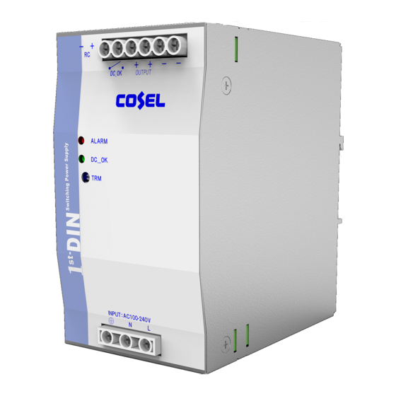
IE048-480 Power Supply Installation Guide Hardware Components The hardware components on the front panel are identified in Figure 1. DC_OK Output Connectors DC Output Connectors Alarm and DC_OK LEDs TRM Screw Ground Connector AC Power Input Connectors Figure 1. Front Panel... -
Page 20: Figure 2: Top Panel
Chapter 1: Overview The hardware components on the top panel are shown in Figure 2. DC Output and Remote DC_OK Controller Connectors Connector Figure 2. Top Panel The hardware components on the bottom panel are identified in Figure 3 on page 21. -
Page 21: Figure 3: Bottom Panel
IE048-480 Power Supply Installation Guide AC Input Connectors Ground Connector Figure 3. Bottom Panel... -
Page 22: Ac Input Connectors
Chapter 1: Overview AC Input Connectors You power the IE048-480 Power Supply with AC power on the two AC N (Neutral) and L (Live) Input connectors on the front panel. The input power range is 90V to 264V. Refer to Table 1 for the wire specifications for the AC input connectors. -
Page 23: Dc Output Connectors
The range is 45.0V to 55.2V. The default is 48.0V. Refer to “TRM Screw for Adjusting the Output DC Voltage” on page 24. Allied Telesis recommends testing the output voltages on the output connectors with a voltmeter and adjusting the output voltage with the TRM screw, if necessary, before connecting powered devices to the power supply. -
Page 24: Trm Screw For Adjusting The Output Dc Voltage
Chapter 1: Overview TRM Screw for Adjusting the Output DC Voltage The DC output connectors on the power supply have a power range of 45.0V to 55.2V. The default is 48V. You can adjust the output voltage with the TRM screw on the front panel. Here are the guidelines: A voltmeter is required to adjust the DC output power. -
Page 25: Remote Control Connector For Turning On Or Off The Dc Output Connectors
IE048-480 Power Supply Installation Guide Remote Control Connector for Turning On or Off the DC Output Connectors On top of the power supply are the Remote Control (RC) connectors. You can use the connectors to remotely turn on or off the DC output connectors, and so remotely power off the devices that are connected to the power supply. -
Page 26: Table 4: Wire Specifications For The Remote Control Connector
Chapter 1: Overview Caution Do not exceed 29.5V on the connector or you may damage it. E132 The wire specifications for the Remote Control connector are given in Table 4. Table 4. Wire Specifications for the Remote Control Connector Wire Description Solid Wire... -
Page 27: Power Alert Dc_Ok Connectors
IE048-480 Power Supply Installation Guide Power Alert DC_OK Connectors The power supply uses the DC_OK connectors on the front panel to alert you to decreases in the DC output power. By connecting an alert device, such as an LED or buzzer, to the connectors, you enable the power supply to immediately alert you if the power on the DC output connectors decreases for any reason. -
Page 28: Leds
Chapter 1: Overview LEDs The status LEDs are defined in Table 6. Table 6. Status LEDs State Description ALARM The power supply is powered off or has shut down. DC_OK ALARM The power supply is operating normally. DC_OK Green ALARM The output voltage is low compared to the set voltage. -
Page 29: Din Rail Installation
To install the product on a wall, install a short length of DIN rail on the wall and then affix the power supply on the rail. Allied Telesis sells packets of five 35x7.5mm DIN rails for wall installations. Refer to Figure 4 and the Allied Telesis web site for details. -
Page 30: Network Devices
The power supply supports a variety of products from Allied Telesis, including the IE200, IE300, and IE340 Series of Industrial Ethernet Switches. For a complete list, refer to the Allied Telesis web site. The power supply has a maximum DC output power of 480W. The output power can be less, depending on AC input voltage and ambient temperature. -
Page 31: Chapter 2 : Beginning The Installation
Chapter 2 Beginning the Installation The chapter contains the following sections: “Reviewing Safety Precautions” on page 32 “Safety Precautions When Working with Electricity” on page 35 “Reviewing Site Requirements” on page 36 “Installation Worksheets” on page 39 ... -
Page 32: Reviewing Safety Precautions
Chapter 2: Beginning the Installation Reviewing Safety Precautions Please review the following safety precautions before beginning the installation procedures. Note Safety statements that have the symbol are translated into multiple languages in the Translated Safety Statements document at www.alliedtelesis.com/library. Warning To prevent electric shock, do not remove the cover. - Page 33 IE048-480 Power Supply Installation Guide Caution Air flow around the unit and through the cooling fins must not be restricted. E20 Note All Countries: Install product in accordance with local and National Electrical Codes. E8 Warning Only trained and qualified personnel are allowed to install or replace this equipment.
- Page 34 E121 Note Allied Telesis does not warrant against lightning or power surges damaging the device. Such damage will be the responsibility of the equipment owner.
-
Page 35: Safety Precautions When Working With Electricity
IE048-480 Power Supply Installation Guide Safety Precautions When Working with Electricity Please review the following additional safety guidelines before beginning the installation procedure. Disconnect all power by turning off the circuit breakers before installing or removing the device or when working with the power supplies. -
Page 36: Reviewing Site Requirements
Do not place objects on top of the power supply. Mounting orientations affect maximum operating temperature capability. Allied Telesis recommends the vertical mounting orientation. Electromagnetic interference might occur between switches and other devices when multiple switches are powered by a single DC power supply. -
Page 37: Grounding Requirements
If the product overheats in an enclosure that was built without taking into account these factors, the warranty of the product might be voided. Consult Allied Telesis when assistance is needed. The enclosure’s BTU/hour rating must be higher than the total ... -
Page 38: Lightning Protection Requirements
Chapter 2: Beginning the Installation Table 7. Ground Resistivity Recommendations Level Recommendation Best Practice <5 ohms Acceptable 5 to 15 ohms Marginal 15 to 25 ohms Non-compliant >25 ohms Lightning Lightning strikes the ground and follows the paths of least impedance to cause damage. -
Page 39: Installation Worksheets
IE048-480 Power Supply Installation Guide Installation Worksheets This section has the two worksheets for planning the installation and record-keeping. Installation worksheet 1 - Table 8 on page 40: Use this worksheet to record the location of the power supply along with the voltages of the AC input and DC output connectors. -
Page 40: Table 8: Installation Worksheet 1: Ie048-480 Ac/Dc Power Supply
Chapter 2: Beginning the Installation Table 8. Installation Worksheet 1: IE048-480 AC/DC Power Supply Title Description Location Voltage of AC Input (Range 90V to 264V) Voltage of DC Output Connectors (Range 45.0V to 55.2V) Enclosure Manufacturer and Model Name 1. 48V default. -
Page 41: Table 9: Installation Worksheet 2: Powered Devices
IE048-480 Power Supply Installation Guide Table 9. Installation Worksheet 2: Powered Devices Title Description Powered Device #___: Model Name PoE Source Device (Yes/No) Maximum Power Consumption Powered Device #___: Model Name PoE Source Device (Yes/No) Maximum Power Consumption Powered Device #___:... - Page 42 Chapter 2: Beginning the Installation...
-
Page 43: Chapter 3 : Installing The Power Supply
Chapter 3 Installing the Power Supply The procedures in this chapter are listed here: “Power Supply Orientation” on page 44 “Power and Control Wires Guidelines” on page 46 “Installing the Power Supply on a DIN Rail” on page 48 ... -
Page 44: Power Supply Orientation
Chapter 3: Installing the Power Supply Power Supply Orientation The power supply is cooled by convection airflow. The airflow direction is bottom to top. Install the power supply vertically to promote the best possible airflow and cooling. Refer to Figure 5. Figure 5. -
Page 45: Figure 7: Unsupported Table, Desk, Or Shelf Installation
Allied Telesis recommends a minimum space of 25mm between the top and bottom of the power supply and adjacent objects. Allied Telesis also recommends minimum spaces of 15mm on the left and right sides when adjacent objects are non-heating (e.g., walls or cabinets) and 50mm for adjacent heating sources (e.g., switches, routers,... -
Page 46: Power And Control Wires Guidelines
Chapter 3: Installing the Power Supply Power and Control Wires Guidelines The wire specifications for the connectors on the power supply are listed in Table 10. Table 10. Wire Specifications Connector Wire Description AC/DC Input Solid Wire AWG 20 to AWG 10 Connectors (N - Neutral (Diameter 0.8 to 2.6mm) and L - Live) -
Page 47: Figure 9: Wrapping Wire Strands
IE048-480 Power Supply Installation Guide Figure 9. Wrapping Wire Strands For added protection against loose strands, tin stranded wires with solder or use electric wire ferrules. Do not route wires on the floor or other areas where they might ... -
Page 48: Installing The Power Supply On A Din Rail
Chapter 3: Installing the Power Supply Installing the Power Supply on a DIN Rail The IE048-480 Power Supply comes with a DIN rail bracket on the back panel for 35x7.5mm or 35x15mm rails. Review the following guidelines before installing the power supply: Depending on the installation site, it may be easier to wire the ... - Page 49 Visually inspect the bracket to verify that the DIN rail is now fitted into the top and bottom bracket slots. Note Allied Telesis recommends installing DIN rail end clamps to the sides of the device to prevent damage or network traffic loss from vibration or shock. End clamps are not available from Allied Telesis.
-
Page 50: Connecting The Ground Wire
Chapter 3: Installing the Power Supply Connecting the Ground Wire This section contains the procedure for installing the ground wire. Warning When installing the equipment, always connect the frame ground wire first and disconnect it last. E11 The procedure requires the following items: One ground wire. -
Page 51: Figure 12: Installing The Ground Wire
IE048-480 Power Supply Installation Guide Figure 12. Installing the Ground Wire... -
Page 52: Connecting The Ac Power Wires
1. Verify that the AC circuit breaker is powered off. 2. Loosen the two N (Neutral) and L (Live) screws on the front panel of the IE048-480 Power Supply and insert the wires into the connectors on the bottom panel. Refer to Figure 13 on page 53. -
Page 53: Figure 13: Installing The Ac Power Wires
IE048-480 Power Supply Installation Guide Figure 13. Installing the AC Power Wires... -
Page 54: Adjusting The Voltage On The Dc Output Connectors
Chapter 3: Installing the Power Supply Adjusting the Voltage on the DC Output Connectors This procedure explains how to verify and adjust the output voltage on the DC output connectors with the TRM screw on the front panel. The range is 45.0V to 55.2V. -
Page 55: Wiring The Dc Output Connectors To Powered Devices
IE048-480 Power Supply Installation Guide Wiring the DC Output Connectors to Powered Devices Connecting a powered device to the IE048-480 Power Supply requires the following items: Two DC power wires. Refer to Table 10 on page 46 for the ... -
Page 56: Figure 14: Installing Dc Output Power Wires
Chapter 3: Installing the Power Supply Caution Do not crossover the wires. Be sure to connect the positive connector on the power supply to the positive connector on the powered device, and the negative connector on the power supply to the negative connector on the powered device. -
Page 57: Wiring The Remote Control (Rc) Connector
IE048-480 Power Supply Installation Guide Wiring the Remote Control (RC) Connector For background information, refer to “Remote Control Connector for Turning On or Off the DC Output Connectors” on page 25. This procedure requires the following: Two RC connector wires. Refer to Table 10 on page 46 for the ... -
Page 58: Wiring The Power Alert Dc_Ok Connector
Chapter 3: Installing the Power Supply Wiring the Power Alert DC_OK Connector For background information, refer to “Power Alert DC_OK Connectors” on page 27. This procedure requires the following: Two DC_OK connector wires. Refer to Table 10 on page 46 for the ... -
Page 59: Verifying The Power Supply
For example, the SHOW POWER-INLINE command displays the power budgets on IE200, IE300, and IE340 series Ethernet switches from Allied Telesis. Refer to their installation or management software user guides for instructions. - Page 60 Chapter 3: Installing the Power Supply...
-
Page 61: Chapter 4 : Troubleshooting
Chapter 4 Troubleshooting This chapter provides suggestions on how to troubleshoot the IE048-480 Power Supply should a problem occur. Note For further assistance, please contact Allied Telesis Technical Support at www.alliedtelesis.com/support. Problem 1: The ALARM and DC_OK LEDs are both off. - Page 62 Graph - Operating Properties and Ambient Temperature” on page 70. Try replacing the power supply. Problem 3: The IE048-480 Power Supply is not supplying power to a powered device. Solutions: Try the following: Verify that the IE048-480 Power Supply is operating normally by ...
- Page 63 Try replacing the powered device. If the new device works, than the problem is with the first device. Problem 4: A PoE switch powered by the IE048-480 Power Supply is not supporting all its PoE devices. Possible causes are listed here: The switch has a technical problem.
- Page 64 Chapter 4: Troubleshooting Solutions: Try the following: Inspect the ALARM LED on the IE048-480 Power Supply. If it is on, refer to Problem 2. Refer to the switch’s installation guide for troubleshooting suggestions for PoE devices.
-
Page 65: Appendix A: Technical Specifications
Appendix A Technical Specifications This appendix contains the following sections: “Physical Specifications” on page 66 “Power Specifications” on page 67 “Environmental Specifications” on page 69 “Derating Graph - Operating Properties and Ambient Temperature” on page 70 “Device Dimensions”... -
Page 66: Physical Specifications
If the product overheats in an enclosure that was built without taking into account these factors, the warranty of the product might be voided. Consult Allied Telesis when assistance is needed. -
Page 67: Power Specifications
IE048-480 Power Supply Installation Guide Power Specifications The power input and output specifications are listed in Table 15 and Table 16. Table 15. Input Power Specifications 90 to 264Vac or 98 to 350Vdc Voltage 115Vac 4.6A typ. Current 230Vac 2.3A typ. - Page 68 Appendix A: Technical Specifications Table 16. Output Power Specifications (Continued) 0° to 70°C <120mVp-p Ripple -25° to 0°C <240mVp-p Io=0 - 30% <750mVp-p 0° to 70°C <150mVp-p Ripple Noise -25° to 0°C <300mVp-p Io=0 - 30% <750mVp-p 2kV, 50 to 1,000ms, +0~360° Line Noise Tolerance 0°...
-
Page 69: Environmental Specifications
IE048-480 Power Supply Installation Guide Environmental Specifications Table 17. Environmental Specifications Operating Temperature Range -25° to 70°C Storage Temperature Range -40° to 85°C Operating Humidity Range 20% to 90% RH, non-condensing Storage Humidity Range Operating Altitude 5,000m Cooling Method Air Convention 40°C. -
Page 70: Derating Graph - Operating Properties And Ambient Temperature
Appendix A: Technical Specifications Derating Graph - Operating Properties and Ambient Temperature The input voltages (Vin) in the derating graph in Figure 17 include a tolerance of +10% nominal value. The derating properties correspond to a vertically mounted device. The operational ambient temperature varies depending on mounting orientation. -
Page 71: Device Dimensions
IE048-480 Power Supply Installation Guide Device Dimensions 124mm (4.88 in.) 117mm 70mm (2.76 in.) (4.61 in.) Figure 18. IE048-480 Power Supply Dimensions... - Page 72 Appendix A: Technical Specifications...
Need help?
Do you have a question about the IE048-480 and is the answer not in the manual?
Questions and answers