Table of Contents
Advertisement
Quick Links
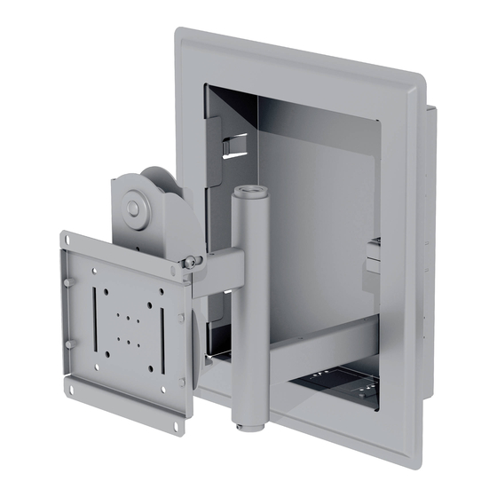
Installation and Assembly:
In-wall Mount for 32" to 71" Flat Panel Displays
Model#
IM760P, IM760P-S
IM760PU, IM760PU-S 32" to 65" (81 to 165 cm)
IM760PU
IM760PU-S
2300 White Oak Circle • Aurora, Il 60502 • (800) 865-2112 • Fax: (800) 359-6500 • www.peerless-av.com
Display size range
32" to 71" (81 to 180 cm)
Maximum UL Load Capacity: 200 lb (90.7 kg)
IM760P
IM760P-S
ISSUED: 12-04-07 SHEET #: 095-9279-6 03-01-13
This product is intended for use with UL
Listed products and must be installed by a
qualifi ed professional installer.
Advertisement
Table of Contents

Related Manuals for peerless-AV IM760P


Summary of Contents for peerless-AV IM760P
- Page 1 IM760PU, IM760PU-S 32" to 65" (81 to 165 cm) Maximum UL Load Capacity: 200 lb (90.7 kg) IM760P IM760P-S IM760PU IM760PU-S 2300 White Oak Circle • Aurora, Il 60502 • (800) 865-2112 • Fax: (800) 359-6500 • www.peerless-av.com ISSUED: 12-04-07 SHEET #: 095-9279-6 03-01-13...
-
Page 2: Table Of Contents
NOTE: Read entire instruction sheet before you start installation and assembly. WARNING • Do not begin to install your Peerless product until you have read and understood the instructions and warnings contained in this Installation Sheet. If you have any questions regarding any of the instructions or warnings, please call Peerless customer care at 1-800-865-2112. -
Page 3: Parts List
Before you begin, make sure all parts shown are included with your product. Parts List IM760P IM760P-S IM760PU IM760PU-S Description Qty. Part # Part # Part # Part # arm assembly 095-P1145 095-C4145 095-P1145 095-C4145 in-wall box 095-P1989 095-C4989 095-P1989... - Page 4 Part List Continued Parts may appear slightly different than illustrated. ASSEMBLY ADAPTER PLATE Used with specifi c mounts only 4 of 12 ISSUED: 12-04-07 SHEET #: 095-9279-6 03-01-13...
-
Page 5: Installation To Wood Stud Wall
Remove drywall inside cut outline. fi g. 1.1 Display center with models TOP CUT LINE IM760P and IM760P-S: Center of adapter plate will be located 6" (152mm) below the top cut line. 14.5"... - Page 6 Installation to Wood Stud Wall (continued) WARNING • Installer must verify that the supporting surface will safely support the combined load of the equipment and all attached hardware and components. • Tighten wood screws so that wall plate is fi rmly attached, but do not overtighten. Overtightening can damage the screws, greatly reducing their holding power.
-
Page 7: Installing Arm To In-Wall Box
Installing Arm to In-wall Box Insert arm axle (C) through arm assembly (A) as shown in fi gure 2.1. Position arm axle (C) and arm assembly (A) into axle support bracket of in-wall box (B) then seat arm axle through bottom hole of in-wall box as shown in fi gure 2.2. Secure arm axle to in-wall box using four M5 x 12mm phillips screws (L) as shown in fi... -
Page 8: Disassemble Mounting Plate
Attaching Adapter Plate to Display with ® VESA Mounting Pattern NOTE: For installing display using universal adapter plate, skip to step 5. Identify VESA mounting pattern on back of your display and choose hole pattern on adapter plate and required fasteners as shown in fi... - Page 9 Installing Universal Adapter Plate to Display Using the hole pattern shown in detail 1, attach the adapter plate to universal adapter plate (T) with four M10 x 17mm screws (X) as shown. Tighten screws using 6mm al- len wrench (Y). LARGE HOLE PATTERN HOLES...
- Page 10 For Flat Back Display Begin with the shortest length screw, hand thread through multi-washer and adapter bracket into display as shown below. Screw must make at least three full turns into the mounting hole and fi t snug into place. Do not over tighten.
-
Page 11: Installing And Removing Flat Panel Display
Adjustment of Flat Panel Display Adjustment of Flat Panel Display TILT Adjustment: Adjust tension knob on side of FOR PORTRAIT OR LANDSCAPE Display mount to desired tension to enable tilt adjustment ORIENTATION: Remove two M5 x 12mm screws, and balance your display size and weight as one M5 x 6mm screw and rotation block from top of shown in fi... -
Page 12: Cable Management
Cable Management For optional installation of electrical gang box, access plates located on the bottom or top of in-wall box can be temporarily removed to install electrical gang box as shown in fi gure 9.1. ACCESS PLATE fi g. 9.1 DISPLAY NOT SHOWN FOR CLARITY Insert up to eight cable management clips (J) into the desired positions in the arm assembly and in-wall box as shown in fi...
Need help?
Do you have a question about the IM760P and is the answer not in the manual?
Questions and answers