Table of Contents
Advertisement
Quick Links
1) Warnings
DO NOT OPEN WHEN AN EXPLOSIVE
ATMOSPHERE IS PRESENT
DO NOT OPEN WHEN ENERGISED
POTENTIAL ELECTROSTATIC CHARGING
HAZARD - CLEAN ONLY WITH A DAMP
CLOTH
HIGH VOLTAGE SHOCK HAZARD. WAIT 5
MINUTES AFTER REMOVING POWER
BEFORE OPENING THE ENCLOSURE
Avertissement:
NE PAS OUVRIR UN PRESENCE
D'ATMOSPHERE EXPLOSIVE
NE PAS OUVRIR ENERGIE
DANGER POTENTIEL CHARGE
ÉLECTROSTATIQUE - NETTOYER
UNIQUEMENT AVEC UN CHIFFON HUMIDE
HAUT TENSION, RISK DE CHOC.
ATTENDEZ 5 MINUTES APRES AVOIR
DEBRANCHE L'ALIMENTATION AVANT
D'OUVRIR LA BOITIER
2) Rating & Marking Information
2.1 ATEX / IECEx certification
The E2xC1LD2 combined alarm horn and LED beacon
complies with the following standards:
EN60079-0:2012+A11:2013 / IEC60079-0: ed. 6.0 (2011-06)
EN60079-15:2010 / IEC60079-15: ed. 4.0 (2010-01)
EN60079-31:2014 / IEC60079-31:2013 ed. 2.0 (2013-11)
Certificate No.
DEMKO 06ATEX 0421554X
IECEx ULD 14.0012X
The E2xC1LD2 combined alarm horn and LED beacon is
rated as follows:
II 3G Ex nA IIC Gc T3 Ta -20°C to +55°C
II 3D Ex tc IIIC Dc T105°C Ta -20°C to +55°C
II 3D Ex tc IIIC Dc T90°C Ta -20°C to +40C
CE Marking
0518
_______________________________________________________________________________________________________________________________
European Safety Systems Ltd. Impress House, Mansell Road, Acton, London W3 7QH
Document No. D209-00-511-IS-SC
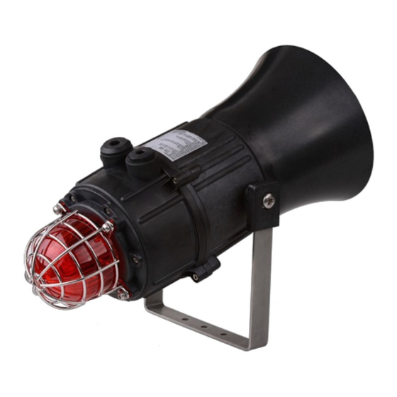
E2xC1LD2R & E2xC1LD2F Combined Sounder & Beacon
For use in Hazardous Locations
E2xC1LD2F
Issue C
13-06-17
INSTRUCTION MANUAL
E2xC1LD2R
Zones, Gas / Dust Groups and Temperature
Classification
When connected to an approved system the E2XS1 alarm
horn may be installed in:
Zone 2 explosive gas air mixture not likely to occur
in normal operation, and if it does, it will only exist
for a short time.
Zone 22 explosive dust air mixture not likely to occur
in normal operation, and if it does, it will only exist
for a short time.
May be used with gases in groups:
Group IIA
Group IIB
Group IIC
Having a temperature classification
(for Gas applications) of:
T1
450ºC
T2
300ºC
T3
200ºC
May be used with Dust types:
Group IIIA
Group IIIB
Group IIIC
Maximum Surface Temperature for Dust Applications:
105ºC
90ºC (up to 40ºC ambient only)
Installation must be carried out in compliance with the latest
issue of the following standards:
EN60079-14 / IEC60079-14: Explosive atmospheres -
Electrical installations design, selection and erection
EN60079-10-1 / IEC60079-10-1: Explosive atmospheres -
Classification of areas. Explosive gas atmospheres
EN60079-10-2 / IEC60079-10-2: Explosive atmospheres –
Classification of areas. Explosive dust atmospheres
sales@e-2-s.com
www.e-2-s.com
Sheet 1 of 8
propane
ethylene
hydrogen / acetylene
combustible flyings
non-conductive dust
conductive dust
Tel: +44 (0)208 743 8880
Fax: +44 (0)208 740 4200
Advertisement
Table of Contents

Subscribe to Our Youtube Channel
Related Manuals for E2S E2 C1LD2F Series


Summary of Contents for E2S E2 C1LD2F Series
- Page 1 INSTRUCTION MANUAL E2xC1LD2R & E2xC1LD2F Combined Sounder & Beacon For use in Hazardous Locations E2xC1LD2F E2xC1LD2R 1) Warnings Zones, Gas / Dust Groups and Temperature DO NOT OPEN WHEN AN EXPLOSIVE Classification ATMOSPHERE IS PRESENT DO NOT OPEN WHEN ENERGISED When connected to an approved system the E2XS1 alarm ...
-
Page 2: Special Conditions Of Use
2.2 NEC Class / Zone ratings US 2.6 Electrical Ratings The E2xC1LD2 combined alarm horn and LED beacon Beacon Sounder Part No. Voltage complies with the following standards: Current Current E2xC1LD2FDC024 / 18-30Vdc 346mA 284mA UL 60079-0-2013 E2xC1LD2RDC024 UL 60079-15-2013 E2xC1LD2FDC048 / 42-54Vdc 115mA... -
Page 3: Cable Connections
large bracket adjustment screws on the side of the unit must 6) Selection of Cable, Cable Glands, Blanking be fully tightened to ensure that the unit cannot move in Elements & Adapters service. When selecting the cable size, consideration must be given to the input current that each unit draws (see Table 1), the number of sounders on the line and the length of the cable runs. - Page 4 care should be taken to dress the wires so that when the 12.2 Stage Switching cover is inserted into the chamber the wires do not exert excess pressure on the terminal blocks. This is particularly 12.2.1 Units First Stage Tones important when using cables with large cross sectional areas such as 2.5mm².
-
Page 5: Wiring Diagrams
10.2 Stage Switching 10.2.1 Units First Stage Tones Stage one (S1) Operation Simply connect the supply voltage to the + and - supply terminals, (see fig. 10.2.2 DC Units Second & Third Stage Tone Selection Stage two (S2) Operation Fig. 4b AC Beacon Terminals Power +ve and –ve, 10) DC Wiring link a -ve supply line to the... -
Page 6: Line Monitoring
terminal plugs and fit the resistor across the two terminal S2 S3 plugs before refitting them to the PCBA as shown in Fig. 9b. A spacing of at least 1/16” (1.58mm) must be provided through air and over surfaces between uninsulated live parts. Fig. - Page 7 The Beacon lens cover is interchangeable, contact E2S Ltd for a replacement lens cover available in various colours. _______________________________________________________________________________________________________________________________ European Safety Systems Ltd. Impress House, Mansell Road, Acton, London W3 7QH sales@e-2-s.com...
-
Page 8: Tone Table
14) Tone Table Switch Stage 1 Frequency Description Stage 2 Stage 3 1 2 3 4 5 6 340Hz Continuous 0 0 0 0 0 0 Tone 2 Tone 5 800/1000Hz @ 0.25 sec Alternating 1 0 0 0 0 0 Tone 17 Tone 5 500/1200Hz @ 0.3Hz sec...
Need help?
Do you have a question about the E2 C1LD2F Series and is the answer not in the manual?
Questions and answers