Advertisement
Quick Links
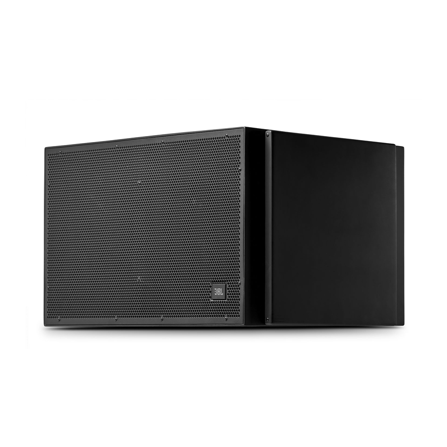
VLA-C125S-ACC Cardioid Kit Installation Instructions
One Cardioid Kit is intended for use with 3 VLA-C125S speakers, in cardioid configuration (two front-
facing and one rear-facing speakers), for use with both gray and black colors.
Contents:
VLA-C125S-ACC Cardioid Kit Contents :
Description
Qty
Gland Nut Cover
4
Gland Nut
2
Jumper Cable
2
Cover, Black
2
Cover, Gray
2
Advertisement

Related Manuals for Harman JBL VLA-C125S-ACC Cardioid Kit


Summary of Contents for Harman JBL VLA-C125S-ACC Cardioid Kit
- Page 1 VLA-C125S-ACC Cardioid Kit Installation Instructions One Cardioid Kit is intended for use with 3 VLA-C125S speakers, in cardioid configuration (two front- facing and one rear-facing speakers), for use with both gray and black colors. Contents: VLA-C125S-ACC Cardioid Kit Contents : Description Gland Nut Cover Gland Nut...
- Page 2 Configuration: These instructions presume a Front-Firing Top Unit, Rear-Firing Middle Unit, and Front-Firing Bottom Unit. However, it can also be utilized for Front/Front/Rear and Rear/Front/Front configurations simply by wiring each unit in accordance with whether it is front-firing or rear-firing. DSP Presets: There is a cardioid preset in the master DSP preset folder for VLA Compact speakers.
- Page 3 Remove washer from gland nut, add Gland Nut Cover to cable and replace washer and tighten around gland nut. Do not tighten the main gland nut yet.
- Page 4 Attach Wires to top/bottom connector and tighten securely: Red: 1+ Black: 1- White: 2+ Green: 2- Tighten gland nut as close to the end of the cable sleeve as possible by tightening outer nut to ensure water tight seal:...
- Page 5 Replace Screws and tighten: Repeat same steps for next unit (opposite firing), using the other end of the jumper cable. Note: make sure enclosure orientation is correct (opposite facing with correct top/bottom orientation). Once the terminal cover is removed, the terminal will come loose from the enclosure in order to reach the jumper wire.
- Page 6 Bottom and Middle units are connected: Repeat the same process for remaining unit.
- Page 7 Configuring the Input Cup Connections: Main front firing unit: DSP Ch1: Top front firing unit to LF 4Ω ± DSP Ch2: Bottom front firing unit to Cardioid In/Out Front ± DSP Ch3: Rear firing unit to Cardioid In/Out Rear ± Return cover with gland nut provided:...
- Page 8 Front firing cardioid unit: Connect Front/Thru to “LF 4Ω” or Cardioid In/Out Front to LF 4Ω ± Rear firing cardioid unit: Connect “Cardioid In/Out REAR to “LF 4Ω”...
- Page 9 Use cover from Cardioid Kit to seal input cup: VLA-C125S-ACC Kit Instructions Rev A © 2019 Harman International www.jblpro.com 11/19...
Need help?
Do you have a question about the JBL VLA-C125S-ACC Cardioid Kit and is the answer not in the manual?
Questions and answers