Table of Contents
Advertisement
Quick Links
USER MANUAL
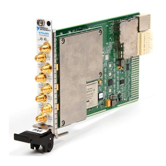
PXIe-6674
PXI Express Timing and Synchronization Module
The PXIe-6674 timing and synchronization module enables you to pass PXI timing and trigger
signals between PXI Express chassis without using the chassis' system timing slot. The
PXIe-6674 can generate and route clock signals between devices in multiple chassis, providing
a method to synchronize multiple devices in a multichassis PXI Express system.
This manual describes the electrical and mechanical aspects of the PXIe-6674 and contains
information concerning its operation and programming.
National Instruments Documentation
The PXIe-6674 User Manual is one piece of the documentation set for your measurement
system. You could have any of several other documents describing your hardware and
software. Use the documentation you have as follows:
•
Measurement hardware documentation—This documentation contains detailed
information about the measurement hardware that plugs into or is connected to the
computer. Use this documentation for hardware installation and configuration
instructions, specifications about the measurement hardware, and application hints.
•
Software documentation—Refer to the NI-Sync Help, available at ni.com/manuals.
You can download NI documentation from ni.com/manuals.
Related Documentation
The following documents contain information that you might find helpful as you read this
manual:
•
PICMG 2.0 R3.0, CompactPCI Core Specification, available from PICMG at
www.picmg.org.
•
PXI Specification, Revision 2.1, available from www.pxisa.org.
•
NI-VISA User Manual, available form ni.com/manuals.
•
NI-VISA Help, included with the NI-VISA software.
•
NI-Sync User Manual, available from ni.com/manuals.
Contents
Introduction............................................................................................................................... 2
What You Need to Get Started..........................................................................................2
Unpacking......................................................................................................................... 3
Advertisement
Table of Contents

Related Manuals for National Instruments PXIe-6674


Summary of Contents for National Instruments PXIe-6674
- Page 1 PXIe-6674 PXI Express Timing and Synchronization Module The PXIe-6674 timing and synchronization module enables you to pass PXI timing and trigger signals between PXI Express chassis without using the chassis' system timing slot. The PXIe-6674 can generate and route clock signals between devices in multiple chassis, providing a method to synchronize multiple devices in a multichassis PXI Express system.
-
Page 2: Table Of Contents
PXI Express chassis and other PXI chassis or non-PXI systems. This is done without using the system timing slot in your PXI Express chassis. The PXIe-6674 module generates and routes clock signals between devices in multiples chassis, providing a method for synchronizing multiple devices in a PXI Express system. -
Page 3: Software Programming Choices
Do not operate the product in a manner not specified in this document. Misuse of the product can result in a hazard. You can compromise the safety protection built into the product if the product is damaged in any way. If the product is damaged, return it to National Instruments for repair. - Page 4 Working voltage is the highest rms value of an AC or DC voltage that can occur across any particular insulation. MAINS is defined as a hazardous live electrical supply system that powers hardware. Suitably rated measuring circuits may be connected to the MAINS for measuring purposes. 4 | ni.com | PXIe-6674 User Manual...
-
Page 5: Installing And Configuring
Power off and unplug the chassis. Locate the desired slot in your PXI Express chassis. The PXIe-6674 can be placed in any PXI Express slot, as indicated by the glyph in Figure 1. -
Page 6: Configuring The Module
The two LEDs on the front panel provide information about module status. The front panel descriptions in the Hardware Overview describe the LEDs in greater detail. Hardware Overview This chapter presents an overview of the hardware functions of the PXIe-6674. Figure 2. page 7 provides a functional overview of the PXIe-6674 hardware. - Page 7 Comparator PCI Express Interface PFI 2 Threshold PFI 3 Driver/ Comparator PFI 3 Threshold LVDS Driver/ Receiver PFI 4 Driver/ Comparator PFI 4 Threshold PFI 5 Driver/ Comparator PFI 5 Threshold PXIe-6674 User Manual | © National Instruments | 7...
-
Page 8: Pxie-6674 Front Panel And Led
PFI 0/ LVDS PFI 1/ LVDS PFI 2/ LVDS PFI 3/ LVDS PFI 4/ LVDS PFI 5/ LVDS 1. Access LED 4. PFI<0..5>/PFI_LVDS<0..2> Connectors 2. Active LED 5. CLKIN Connector 3. CLKOUT Connector 8 | ni.com | PXIe-6674 User Manual... - Page 9 Caution Connections that exceed any of the maximum ratings of input or output signals on the PXIe-6674 can damage the module and the computer. NI is not liable for any damage resulting from such signal connections. Table 2. Access LED...
-
Page 10: Active Led
Caution If the Access LED is observed to be solid red, a hardware failure has been detected that may impact the performance of the PXIe-6674. Contact National Instruments for support. Active LED You can set the Active LED to amber. - Page 11 The PXI trigger bus consists of eight digital lines shared from chassis) among all slots in the PXI Express chassis. The PXIe-6674 can route a wide variety of signals to and from these lines. Note PXI_TRIG<0..5> are also known as RTSI<0..5>...
-
Page 12: Generating And Routing Clocks
LVDS signaling. The remainder of this chapter describes how these signals are used, acquired, and generated by the PXIe-6674 hardware, and explains how you can route the signals between various locations to synchronize multiple measurement devices and PXI chassis. - Page 13 CLKIN can be routed to the FPGA and used as a trigger synchronization clock inside the FPGA. Because the PXIe-6674 is not designed for use in the system timing slot, it can not drive CLKIN to PXI_CLK10_IN for overdriving PXI_CLK10 and PXIe_CLK100. The PXIe-6674T is required for this functionality.
-
Page 14: Routing Trigger Signals
NI-Sync software will select the low speed or high speed driver automatically based on the source connected to CLKOUT. Routing Trigger Signals The PXIe-6674 has versatile trigger routing capabilities. It can route signals to and from the front panel, the PXI_STAR trigger, the PXI_TRIG triggers, and PXIe_DSTARB/ PXIe_DSTARC. - Page 15 15 and Figure 5. on page 16 summarize the routing features of the PXIe-6674. The remainder of this chapter details the capabilities and constraints of the routing architecture. Figure 4. High-Level Schematic of PXIe-6674 Signal Routing Architecture Selection...
- Page 16 Refer to the Choosing the Type of Routing section for more information on synchronous routing versus asynchronous routing. Figure 6. on page 17 summarizes the sources and destinations of the PXIe-6674. 16 | ni.com | PXIe-6674 User Manual...
- Page 17 Note Terminating the signals with a 50 Ω resistance is recommended when the source is another PXIe-6674 or any other source with a 50 Ω output. The voltage thresholds for the front-panel PFI inputs are programmable. The input signal is generated by comparing the input voltage on the PFI connectors to the voltage output of software-programmable DACs.
- Page 18 The PFI synchronization clock is the same for all routing operations in which PFI<0..5> or PFI_LVDS<0..2> is defined as the output, although the divide-down ratio for this clock (full rate, first divider, second divider) may be chosen on a per route basis. 18 | ni.com | PXIe-6674 User Manual...
- Page 19 PXI triggers convenient in situations where you want, for instance, to start an acquisition on several devices at the same time because all modules will receive the same trigger. PXIe-6674 User Manual | © National Instruments | 19...
- Page 20 The star trigger lines are bidirectional, so signals can be sent to the system timing slot from a module in another slot or from the system timing slot to the other module. 20 | ni.com | PXIe-6674 User Manual...
-
Page 21: Choosing The Type Of Routing
PXIe_DSTARC are one directional. The PXI Express Specification requires PXI Express chassis to limit the skew between any two PXIe_DSTAR routes to 150 ps. The PXIe-6674 receives PXIe_DSTARB and can route it as a trigger source. The PXIe-6674 can independently select from the following sources to be routed to PXIe_DSTARC: •... - Page 22 Propagation delay of the signal through the PXIe-6674. • Time for the receiver to recognize the signal. Both the source and the destination of an asynchronous routing operation on the PXIe-6674 can be any of the following lines: • Any front panel PFI pin (PFI<0..5>) as single ended.
- Page 23 CtoQ Trigger Output The PXIe-6674 board supports synchronous routing to either the rising or falling edge of the synchronization clock. In addition, the polarity of the destination signal can be inverted, which is useful when handling active-low digital signals. Synchronous routing can be useful for eliminating skew when sending triggers to several destinations.
- Page 24 Info Code ni.com/info SyncTriggerRouting Possible sources for synchronous routing with the PXIe-6674 include the following sources: • Any front panel PFI pin as single ended. • Any front panel PFI pin as LVDS.
-
Page 25: Calibration
OXCO Frequency The OCXO frequency can be varied over a small range. The output frequency of the OCXO is adjusted using this constant to meet the specification listed in the PXIe-6674 Specifications. PXI_CLK10 Phase When using the PLL to lock PXI_CLK10 to an external reference clock, the phase between the clocks can be adjusted. -
Page 26: Legal Information
Changes or modifications not expressly approved by National Instruments could void the user's right to operate the hardware under the local regulatory rules. Caution To ensure the specified EMC performance, operate this product only with double-shielded cables (such as RG-223 double-shielded cables) and accessories. - Page 27 OR ERROR FREE. In the event that you and NI have a separate signed written agreement with warranty terms covering the products, then the warranty terms in the separate agreement shall control. PXIe-6674 User Manual | © National Instruments | 27...
-
Page 28: Copyright
National Instruments Corporation. National Instruments respects the intellectual property of others, and we ask our users to do the same. NI software is protected by copyright and other intellectual property laws. Where NI... -
Page 29: Patents
Other product and company names mentioned herein are trademarks or trade names of their respective companies. Members of the National Instruments Alliance Partner Program are business entities independent from NI and have no agency, partnership, or joint-venture relationship with NI. -
Page 30: Export Compliance Information
Export Compliance Information Refer to the Export Compliance Information at ni.com/legal/export-compliance the National Instruments global trade compliance policy and how to obtain relevant HTS codes, ECCNs, and other import/export data. WARNING REGARDING USE OF NATIONAL INSTRUMENTS PRODUCTS YOU ARE ULTIMATELY RESPONSIBLE FOR VERIFYING AND VALIDATING THE...
Need help?
Do you have a question about the PXIe-6674 and is the answer not in the manual?
Questions and answers