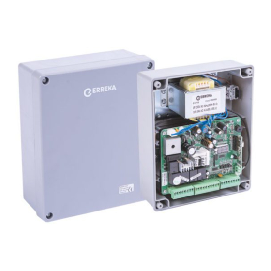
Erreka SMART-D201 Quick Installation And Programming Manual
Hide thumbs
Also See for SMART-D201:
- Quick installation manual (5 pages) ,
- Quick installation manual (28 pages)
Table of Contents
Advertisement
Quick Links
SMART-D201(M)
Quick installation and programming guide
This quick guide is a summary of the complete installation guide. The guide contains safety warnings and other
explanations that must be taken into account. The most recent versions of this guide and the installation manual
are available at the "Downloads" section on Erreka's website. http://www.erreka-automation.com
IMPORTANT
The options and functions described in this guide apply for the firmware version indicated on the circuit. The
NOTE
firmware, as part of a process of continuous improvement, is subject to new functionalities or upgrades being
included as a result of new versions which are not necessarily compatible with previous ones. For this reason,
some options or functions may differ or be unavailable if your firmware is older than shown in this guide.
Elements of the complete installation
NOTE: this control panel is valid for swing
gate operators, for example:
• TEMIS (no encoder or limit switches)
• KAIROS (with or without limit switches)
• ARES 24V
Electrical cables
A:
Main power supply
B/F: Flashing light with antenna
C:
Photocells (Rx/Tx)
D:
Pushbutton/key switch
E:
Operator
VERY IMPORTANT: the TC closing stopper and
the TA opening stoppers must be installed.
ANT Cable connectors for antenna
EC
Electrolock 24 VDC
A.T. Double-leaf opening pushbutton
A.P. Single-leaf opening pushbutton
DEST Flashing light
(ERREKA LUMI)
Configure DIP1 as shown in
figure
FT1
Exterior safety device (ERREKA
FT06 photocell)
FT2
Interior safety device (ERREKA
FT06 photocell)
Peripheral cabling (valid for all cases)
CO
CO
J4
1
2
3
4
5
6
7
M1-
M2+
Lit+
Lit-
Lat+
Lat-
M1+
EC
(24VDC)
DIP1
DEST
FT2
(FT06)
CO
CO
J5
8
9 10 11 12 13 14 15 16 17 18
M2-
5V
S2
GND
Lmt1
Lmt2
GND
Lmt3
Lmt4
GND
S1
A.T.
A.P.
(LUMI)
FT1
(FT06)
English
2 x 1mm
2
J7
ANT
LED2
LED4
LED3
GND
J3
J8
19 20 21 22 23 24 25 26
DKey
SKey
GND
Ph1 PhVcc
GND
Ph2
PhVcc
E307A
P307Z
7
Advertisement
Table of Contents

Summary of Contents for Erreka SMART-D201
- Page 1 This quick guide is a summary of the complete installation guide. The guide contains safety warnings and other explanations that must be taken into account. The most recent versions of this guide and the installation manual are available at the "Downloads" section on Erreka's website. http://www.erreka-automation.com IMPORTANT The options and functions described in this guide apply for the firmware version indicated on the circuit.
- Page 2 15/18 Common PC A1/A2 • Programme F1 for operation without encoder or limit switches (F11). P303W Electricity connection SMART-D201: 230V/50Hz SMART-D201M: 125V/60Hz Trafo Battery connection (BAT): BAT: 2 x 12V / 1,3 - 15Ah • There is no need to incorporate a charger as there is already one in the control panel.
- Page 3 Display indications, LEDs and pushbuttons Pushbuttons: Goes through the options during programming Selects options during programming DOWN Goes back through the options LED Display during programming RF-LEARN Programmes erases DOWN transmitters RF-LEARN LED Azul-Memorización Radio LED2 Pulsador o Selector de llave LEDs: LED3 Fotocélula 1 LED4 Fotocélula 2...
- Page 4 Radio code programming (Roller Code transmitters) The radio card receives Standard Roller Code transmitters: IRIS (IR02, IR04) and LIRA (LR02). It does not receive fixed codes (LUNA/KUMA). 1 Connect the power. 2 While "DL1" is on, hold the 3 Transmitters can be programmed Hold down "RF-LEARN"...
- Page 5 Complete programming chart INITIAL NOTES: F3 menu, trapping force: this parameter must be set to value F31 (for TEMIS and KAIROS operators) or value F32 (for ARES 24V) when programming open/close. After programming open/close, the display shows a figure indicating the current value multiplied x 10 (showing 10 for 1A, 20 for 2A, etc).
- Page 6 Preset Menu Description Options Options or values option FA0: pedestrian opening is not carried out Selecting pedestrian opening FA1: open the single leaf with the transmitter's B button FB0: no pre-warning; the light comes on and the gate Flashing light pre-warning starts to move at the same time FB1: 3 seconds’...


Need help?
Do you have a question about the SMART-D201 and is the answer not in the manual?
Questions and answers