Table of Contents
Advertisement
Quick Links
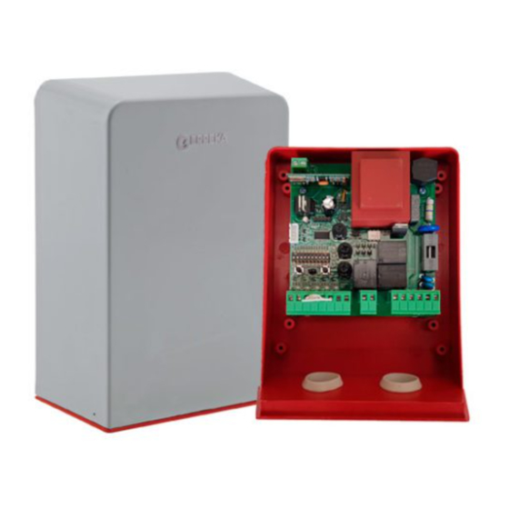
CLEVER03
Quick installation and programming guide
This quick guide is a summary of the complete installation guide. The guide contains safety warnings and other
explanations that must be taken into account. The most recent versions of this guide and the installation
manual are available in the "Downloads" section on Erreka's website.
http://www.erreka-automation.com
IMPORTANT
NOTE
The options and functions described in this guide apply for the firmware version indicated on the circuit. The
firmware, as part of a process of continuous improvement, is subject to new functionalities or upgrades being
included as a result of new versions which are not necessarily compatible with previous ones. For this reason,
some options or functions may differ or be unavailable if your firmware is older than shown in this guide.
ELECTRICAL WIRING:
Element
A: Main power supply
B: Garage light
C: Photocell
D: Pushbutton/wall key
E/F: Operator / Limit switches
G: Antenna
Elements of the complete installation
Nº wires per section
3x1.5mm
2x1.5mm
4x0.5 mm
2x0.5 mm
2
3x1mm
Coaxial cable 50k (RG-58/U) 5m
Maximum length
2
30m
2
30m
2
30m
2
25m
2
/ 3x0.50mm
8m
English
E311A
5
Advertisement
Table of Contents

Related Manuals for Erreka CLEVER03


Summary of Contents for Erreka CLEVER03
- Page 1 This quick guide is a summary of the complete installation guide. The guide contains safety warnings and other explanations that must be taken into account. The most recent versions of this guide and the installation manual are available in the "Downloads" section on Erreka's website. http://www.erreka-automation.com...
- Page 2 General connections (static): door fully or partially open (or on standby) (flashing slowly): programming error DL14 (static): radio programming (flashing 0.5s): receiving radio code Programming mode e n a b l e d ( p r o g r a m m i n g operation or radio code) FCA contacts closed FCC contacts closed...
- Page 3 Total opening radio code programming 3 Place the DIPs as shown in the figure 5 Place DIP1 and DIP4 in OFF. Ensure JP1 is configured correctly (DIP1=ON, DIP4=ON). DL3 and DL2 DL3 and DL2 remain off. before starting: light up to show programming mode –...
- Page 4 Pedestrian open/close programming This is carried out in the same way as total open/close • DIP1 and DIP3 are used instead of DIP1 and DIP2 programming, with the following differences: • ST2 is used instead of ST1 (except in step 1) Function and mode selection using SW2 (DIP1 = OFF) Modes and functions Option...
Need help?
Do you have a question about the CLEVER03 and is the answer not in the manual?
Questions and answers