Table of Contents
Advertisement
Quick Links
Advertisement
Table of Contents

Summary of Contents for Snap-On MODIS
- Page 1 Display User Manual August 2009 ZEEMS300N Rev. A...
- Page 2 Disclaimer The information, specifications and illustrations in this manual are based on the latest information available at the time of printing. Snap-on reserves the right to make changes at any time without notice. Visit our website at: www.snapon.com/solus (North America) snapondiag.com (Europe)
-
Page 3: Safety Information
Safety Information For your own safety and the safety of others, and to prevent damage to the equipment and vehicles upon which it is used, it is important that the accompanying Safety Information be read and understood by all persons operating, or coming into contact with, the equipment. We suggest you store a copy the book near the unit in sight of the operator This product is intended for use by properly trained and skilled professional automotive technicians. - Page 4 Safety Information Important Safety Instructions Safety messages contain three different type styles. • Normal type states the hazard. Bold type states how to avoid the hazard. • Italic type states the possible consequences of not avoiding the hazard. • An icon, when present, gives a graphical description of the potential hazard. Example: WARNING Risk of unexpected vehicle movement.
-
Page 5: Table Of Contents
Installing the Battery Pack ......................14 Connecting the AC/DC Power Supply ..................14 Charging the Battery Pack......................14 Powering On The MODIS™ Unit....................15 Adjusting Brightness and Contrast ..................... 15 Setting Up to Print ........................16 Connecting to a Computer......................16... -
Page 6: Table Of Contents
Table of Contents Chapter 4: Navigation ......................18 Startup Screen..........................18 Screen Layout ..........................19 Main Body........................... 20 Toolbars............................20 Upper Toolbar ........................20 Lower Toolbar ........................22 Status Bar........................... 23 Making Selections ........................23 Easy Scroll..........................24 Screen Messages........................25 Confirmation Messages...................... - Page 7 Table of Contents Prolonging Battery Pack Life ...................... 51 Replacing the Battery Pack ......................51 5-Amp Fuse ..........................51 Fan Filters........................... 52 CompactFlash® (CF) Cards ....................... 53 Liquid Crystal Display (LCD) ...................... 53 Appendix A: Troubleshooting ....................54 Appendix B: Downloading and Installing Software Updates ..........56 Check for Service Upgrades Before Use..................
-
Page 8: Chapter 1 Using This Manual
Using This Manual Chapter 1 This manual contains tool usage instructions. Some of the illustrations shown in this manual may contain modules and optional equipment that are not included on your system. Contact a sales representative for availability of other modules and optional equipment. -
Page 9: Terminology
Using This Manual Conventions 1.1.3 Terminology The term “select” means highlighting a button or menu item using the Thumb Pad and pressing the Y/a button to confirm the selection. Example: Select Reset. • The above statement abbreviates the following procedure: 1. -
Page 10: Additional Manuals
Using This Manual Additional Manuals 1.2 Additional Manuals Tools that work in conjunction with various hardware and software modules have separate manuals available for each of the modules. 1.3 Tool Help Your unit has Tool Help containing reference and procedural information found in this and other tool related user’s manuals. -
Page 11: Chapter 2 Introduction
Figure 2-1 MODIS™ (Modular Diagnostic Information System) The MODIS™ unit is expandable to let you configure the system to meet your specific needs. Optional modules and accessories can be added to further enable you to diagnose problematic components, connectors, and systems. - Page 12 Functional Description 5— Brightness/Contrast (S Button) Adjusts screen brightness and contrast or performs other user-assigned function. 6— Power Button Turns the MODIS™ display unit on and off. 7— Battery Pack 8— Fuse Protects the internal circuitry. 9— Video Graphics Array (VGA) Output Extends display to an optional external monitor.
-
Page 13: Technical Specifications
Introduction Technical Specifications 2.2 Technical Specifications Display: Liquid Crystal Display (LCD) 640 x 480 resolution 256 Colors ® CompactFlash Card Slot: PCMCIA standard compliant ® CompactFlash Card CF Type I Top slot has I/O support Side slot is for approved use only (no hot swapping) Battery: Nickel-metal hydride Fuse:... -
Page 14: The Stand
2.3 The Stand The MODIS™ unit has a built-in, metal stand attached to the back. When the stand is not in use, it is secured to the back of the unit by an integrated casing hook. When extended, the stand allows the unit to rest at a 45°... -
Page 15: Thumb Pad
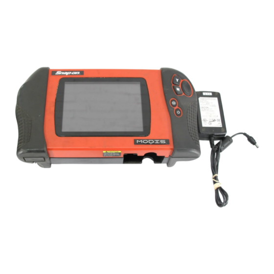
AC/DC power supply • Vehicle auxiliary power cables (12 volt) • Scanner Plug-in cables • Battery pack (rechargeable) 2.5.1 AC/DC Power Supply The MODIS™ unit can be powered from a wall socket using the AC/DC power supply and power cord (Figure 2-5). -
Page 16: Vehicle Auxiliary Power Cables
The AC/DC power supply also powers battery pack charging. Refer to “Charge Battery” on page 46 for details. 2.6 Vehicle Auxiliary Power Cables The MODIS™ unit can be powered from a vehicle using the Lighter Power Cable (Figure 2-6) or the Battery Power Cable (Figure 2-7). NOTE: When receiving power from the vehicle battery, the Battery Power Cable is used with the Lighter Power Cable. -
Page 17: Scanner Plug-In Cables
Introduction Scanner Plug-in Cables 2.7 Scanner Plug-in Cables The MODIS™ unit can be powered from a vehicle using the Scanner™ Plug-in data cable (Figure 2-8) in conjunction with various vehicle adapters. Figure 2-8 Sample data cable Refer to your manufacturer-specific Vehicle Communication Software (VCS) manual for details. -
Page 18: Chapter 3 Getting Started
Getting Started Chapter 3 This section explains how to get started using your MODIS™ unit. 3.1 Supplying Power to the Unit Your MODIS™ unit can be powered using the following sources: • AC/DC power supply Vehicle auxiliary power cables •... -
Page 19: Vehicle Auxiliary Power Cables
After the start up sequence is complete, the main menu screen displays. 3.3 Vehicle Auxiliary Power Cables The auxiliary power cables can be used to provide power from the vehicle to your MODIS™ unit. Figure 3-2 Sample Vehicle auxiliary power cables connected 1—... -
Page 20: Scanner Plug-In Cables
3.4 Scanner Plug-in Cables The Scanner™ Plug-in data cable in conjunction with various vehicle adapters can provide power from the vehicle to your MODIS™ unit (Figure 3-4). Figure 3-4 Sample Scanner™ Plug-in data cable Refer to your manufacturer-specific vehicle communication manual for instructions. -
Page 21: Installing The Battery Pack
To charge the battery pack: 1. Make sure your battery pack is installed properly. 2. Connect the AC/DC power supply to your MODIS™ unit and plug the other end into an appropriate wall socket. 3. Power on your unit, if needed. -
Page 22: Powering On The Modis™ Unit
Getting Started Powering On The MODIS™ Unit 3.9 Powering On The MODIS™ Unit Follow the instructions below to power on your unit. To power on your unit: 1. Connect a power supply to your unit. 2. Press the Power button. -
Page 23: Setting Up To Print
See “Printer” on page 39 for details. 3.12 Connecting to a Computer Connecting your MODIS™ to a computer for file sharing requires the use of the optional ShopStream Connect™ software. ShopStream Connect is a free software program that can be downloaded from the Internet at software.snapon.com. - Page 24 Getting Started Powering Off the Unit To power off the unit: 1. Press the Power button. The “Power off?” confirmation message displays. 2. Press Y/a to turn off the device. The Powering Off graphic displays while the system is shutting down. A long beep sounds as the screen goes black.
-
Page 25: Chapter 4 Navigation
4.1 Startup Screen The startup screen displays when MODIS™ is first powered up, and when you exit from any test (Figure 4-1). The icons on the left side of the display indicate the various tool operations. Use the up b and down d arrows to select from the list of icons. -
Page 26: Screen Layout
Scope Gases Save Data Utilities 4.2 Screen Layout MODIS™ screens (Figure 4-2) typically include the following sections: The upper toolbar and lower toolbar contain test controls. • • The main body displays test data and may contain multiple sections. •... -
Page 27: Main Body
Upper and lower toolbars contain test controls that vary depending on the module and stage of operations. Refer to the module-specific manuals for operating details. To navigate MODIS™ toolbars: 1. Use the Thumb Pad to highlight an item. 2. Press Y/a to select it. - Page 28 Navigation Toolbars The table below details al of the buttons available on the upper toolbar. Table 4-2 Upper toolbar controls Name Button Description Lets you identify a vehicle (for Technical Vehicle ID Service Bulletins only) View Lets you change the way data displays Indicates when the Scanner screen is Scanner active in the Scanner mode...
-
Page 29: Lower Toolbar
Navigation Toolbars Data Buffer The Data Buffer (Figure 4-4) is located just below the upper toolbar buttons in the Multimeter, Scanner, and Scope modules and indicates how much test data is stored. Figure 4-4 Sample Data Buffer 1— Pause button 2—... -
Page 30: Status Bar
Navigation Status Bar The specific controls that display on the lower tool bar vary depending on the active mode and stage of operation. The table below details control options. Table 4-3 Lower toolbar controls Name Button Description Channel number Lets you select the channel to adjust Displays the current test connection for the Probe channel... -
Page 31: Easy Scroll
3. Select a submenu option. NOTE: Menu and submenu options vary by market, as well as by what accessories are installed on your MODIS™ unit. To exit a selection • Press the N/X button to return to the previous menu. -
Page 32: Screen Messages
N/X or the left e and right c arrows (in a figure-8 pattern) to move out of the lower toolbar. Refer to “Easy Scroll” on page 45 for information on activating Easy Scroll. 4.8 Screen Messages The MODIS™ unit displays three types of messages: • Confirmations •... -
Page 33: Chapter 5 Operations
Sample main menu screen 1— Module-specific buttons 2— General system buttons Available buttons and menus vary depending on the modules installed on your MODIS™ unit. 5.2 Scanner The Scanner button (Figure 5-2) activates the scan tool module. Menu selections vary by market. -
Page 34: Component Test
The Component Test button on the main screen (Figure 5-3) accesses Component Testing, Service Bulletins, and Online Info. Figure 5-3 Sample Component Test button menu 5.3.1 Component Testing For Component Testing details, refer to the MODIS™ Component Test User Manual. -
Page 35: Multimeter
Operations Multimeter 5.4 Multimeter The Multimeter button (Figure 5-4) accesses the Graphing Meter and Digital Meter. Figure 5-4 Sample Multimeter button menu and submenu Refer to the Lab Scope Plug-in User Manual for details. 5.5 Scope The Scope button (Figure 5-5) accesses the Lab Scope and Ignition Scope. Figure 5-5 Sample Scope button menu Refer to the Lab Scope Plug-in User Manual for details. -
Page 36: Gases
FGA unit is properly connected. The Flexible Gas Analyzer (FGA) is optional equipment. Figure 5-6 Sample Gases button menu Refer to the MODIS™ Flexible Gas Analyzer User Manual for details. 5.7 Save Data The Save Data button (Figure 5-7) accesses the Data Management screen. Figure 5-7... - Page 37 Operations Save Data The Data Management screen (Figure 5-8) lets you manage the storage memory of your unit and your saved files. Data Management is not module-specific. Figure 5-8 Sample Data Management screen ® 1— Top slot CompactFlash card indicator Displays which CF slot is selected in SETUP.
-
Page 38: Identifying Saved Files
Operations Save Data NOTE: Factory-installed files, identified by a lock icon, cannot be edited, deleted, copied, or moved. 5.7.1 Identifying Saved Files Saved files have the following characteristics: • Type is represented as a three-letter identifier, such as LS(M), where “LS” represents the module source (Lab Scope) and “(M)”... -
Page 39: Editing Saved Files
Operations Save Data NOTE: If you load a BMP file and want to print it, press Y/a. To exit the loaded screen: 1. Press N/X to return to the Data Management screen. 2. Press N/X again to return to the main menu. 5.7.3 Editing Saved Files The EDIT button lets you add notes to saved test data. -
Page 40: Deleting Saved Files
Operations Save Data NOTE: The Keep Entries options are only available when first saving the file. To exit Edit Data screen: • Press N/X to return to the main menu. 5.7.4 Deleting Saved Files The DELETE button lets you delete saved test data. To delete files: 1. -
Page 41: Selecting All Files
Operations Save Data 6. Press Y/a to close the message box. You return to the Data Management screen. NOTE: Factory-installed files and files saved on a CF card in the top slot cannot be copied or moved. 5.7.6 Selecting All Files The SELECT ALL button highlights all saved data so you can delete, move, or copy all the files at once (Figure 5-11). -
Page 42: Setup
The file type of a saved image • NOTE: The Save Data dialog box can also be opened from the MODIS main menu. Refer to “Save Data” on page 39 for details. 5.7.9 Backing up Saved Files You can back up your saved test data to an external source to free internal memory space. Files can be saved to either a CF card in the top slot or a to USB mass storage device (jump drive) connected to the USB port on the top of the unit. -
Page 43: Tool Setup
Operations Utilities Figure 5-14 Sample Utilities menu The following utilities options may be available: • Tool Setup • Gas Bench Setup • System Tools • HDS Units Tool Help • Easy Scroll • Charge Battery • • Connect to PC •... - Page 44 Display As sets how the scale units are displayed (Figure 5-16). Figure 5-16 Display As menu sample For more information refer to the Lab Scope Plug-in User Manual or MODIS™ Flexible Gas Analyzer User Manual. To change the units of measurement: 1.
- Page 45 Operations Utilities Scanner Units Selecting Scanner Units allows you to switch between US Customary and metric units of measurement for parameter values displayed when using the scan tool. To change the Scanner Units: 1. From the main menu, select Utilities > Tool Setup > Scanner Units. The Scanner Units dialog box displays (Figure 5-17).
- Page 46 Refer to “Save Data” on page 29 for details. Printer Selecting Printer lets you set up your MODIS™ unit for printing to various aftermarket printers. Settings include: Manufacturer—configures the MODIS™ unit to print to different types of printers. Available •...
- Page 47 Port—lets you activate the MODIS™ port to which your printer is connected. NOTE: There are several aftermarket IR print adapters available that extend your MODIS™ unit printing. One such compatible third-party adapter is the ACTiSYS model ACT-IR 100M. Contact ACTiSYS Corporation for product details and purchase.
- Page 48 Operations Utilities Time Selecting Time lets you set the time that displays in the Status bar. To set the time: 1. From the main menu, select Utilities > Tool Setup > Time. The Time dialog box displays (Figure 5-22). Figure 5-22 Sample Time dialog box 2.
- Page 49 Operations Utilities Figure 5-23 Sample Brightness/Contrast dialog box 2. Select a function from the drop-down list. The drop-down lists close when Y/a is pressed. 3. Press N/X to close the dialog box. Navigation Prompts Available only in Europe, selecting Navigation Prompts lets you set on-screen control button references to match the hardware.
- Page 50 • Graph • Last Used View Refer to the MODIS™ Scanner Plug-in User Manual for details To select a Scanner View: 1. Select Utilities > Tool Setup > Scanner View. The Scanner View dialog box displays. 2. Press Y/a to display a drop-down list (Figure 5-26).
-
Page 51: Gas Bench Setup
System Restore—lets you reinstall your system software. 5.8.4 Legacy Software The Legacy Software runs the Scanner Plug-in of your MODIS™ unit using an earlier version of the operating system software. It is used to diagnose older vehicles that are not covered in the current database. -
Page 52: Tool Help
Utilities 5.8.6 Tool Help Tool Help provides information from this manual as well as from each of the module-specific manuals currently available with the MODIS™ unit. To use Tool Help: 1. From the main menu, select Utilities > Tool Help. -
Page 53: Charge Battery
The AC/DC power supply is in use. • The MODIS™ unit is powered on. • The MODIS™ unit automatically controls battery pack charging. A Battery/Charging Status indicator icon located on the right side of the status bar (Figure 5-30) shows the charge status. Figure 5-30... -
Page 54: Connect To Pc
If you do not want to wait for the automatic charging system to start, you can manually activate battery pack charging. To manually activate battery charging: 1. Connect the AC/DC power supply to your MODIS™ unit and plug the other end into an appropriate wall socket. 2. Power on your unit, if needed. -
Page 55: Run
A message offering to include your information as a header on your printed pages displays (Figure 5-33). Figure 5-33 Sample Shop Info header printing message 6. Press Y/a or N/X to choose your printing preference. 5.8.12 System Info Selecting the System Info option displays configuration information for your MODIS unit. - Page 56 Operations Utilities To view unit configuration information: 1. Select Utilities > System Info. The System Information screen displays. The left field of the screen shows the information menu and the right field displays the selected information. Navigate the information screens as follows: a.
-
Page 57: Chapter 6 Maintenance
Maintenance Chapter 6 This section describes maintenance for the following MODIS™ parts and accessories: Disposal • Cleaning and damage inspection • Battery pack • • 5-amp fuse • Fan filter ® • CompactFlash (CF) cards • Liquid Crystal Display (LCD) 6.1 Disposal... -
Page 58: Prolonging Battery Pack Life
Maintenance Prolonging Battery Pack Life 6.3 Prolonging Battery Pack Life To maximize the life expectancy of your battery pack when your MODIS™ unit is not being used, do one of the following: • Connect the AC/DC power supply, power on your MODIS™ unit, and activate the battery charger to maintain the battery charge. -
Page 59: Fan Filters
When inserting a new fuse, do not let it fall into the housing. 6.6 Fan Filters The MODIS™ unit uses a filter to reduce dust buildup inside the unit that can reduce screen clarity. The fan filter is located on the back of the unit near the right handgrip (Figure 6-4). -
Page 60: Compactflash® (Cf) Cards
Software updates are released on CF card media. Refer to the instructions accompanying the CF card for installation procedures. NOTE: Save your MODIS™ CF cards. They can be used for data storage. 6.8 Liquid Crystal Display (LCD) The LCD needs to be handled carefully. -
Page 61: Appendix A Troubleshooting
Refer to “Power Sources” on page 8 for details. Battery Pack Discharging During Storage If the battery pack is in your MODIS™ unit when powered off, a slow discharge occurs. Refer to “Prolonging Battery Pack Life” on page 51 for proper battery pack storage. - Page 62 Troubleshooting MODIS™ Unit Overheating MODIS™ Unit Overheating If the internal temperature of your MODIS™ unit reaches 60 °C/140 °F, it powers off automatically. Overheating can occur under the following conditions: Extended use in direct sunlight • Extended use on hot days •...
-
Page 63: Appendix B Downloading And Installing Software Updates
CD-ROM, DVD, or DVD-ROM drive • • USB 2.0 or later • Internet Explorer 6.0 or higher • Internet connection • Adobe Reader software (free download at www.adobe.com/products/reader) A type A/B USB cable is also needed to connect the MODIS unit to the PC. -
Page 64: Verifying Pc System Properties
Downloading and Installing Software Updates Downloading and Installing ShopStream Connect B.2.1 Verifying PC System Properties Follow the procedures below to check your PC system properties and to determine how much free space is available on your hard drive. To check your PC system properties: 1. - Page 65 Downloading and Installing Software Updates Downloading and Installing ShopStream Connect To download the software: 1. From your PC, go to http://diagnostics.snapon.com/scc using your Internet browser. 2. Locate the ShopStream Connect software download. 3. Follow the on-screen instructions. After downloading, use the procedures below to install the ShopStream Connect software onto your PC.
-
Page 66: Downloading Service Upgrades
Downloading and Installing Software Updates Downloading Service Upgrades The Setup Status screen tracks progress as the program installs (Figure B-5). Figure B-5 Sample Setup Status screen 6. When the Complete screen displays, select Finish to close the Install Wizard (Figure B-6). Figure B-6 Sample Complete screen A ShopStream Connect shortcut icon is added to your desktop (Figure B-7), double-click the... -
Page 67: Before You Begin
3. From the MODIS main menu, select Utilities > Connect to PC to place the tool in Connect to PC mode. 4. Remove the left handgrip from the MODIS unit and connect the small end of the USB cable to the port located above the CF card. - Page 68 Figure B-9 Sample removable disk window 6. Double-click the desktop icon to launch ShopStream Connect (Figure B-7). 7. Once ShopStream Connect opens; select Tools > Update Software > MODIS from the Menu bar (Figure B-10). Figure B-10 Sample Update Software menu When connectivity is established with the Snap-on Web server, a check for updates confirmation message displays (Figure B-11).
- Page 69 The upgrade is now downloaded, but not installed. The installation process automatically begins when MODIS is powered on. 12. Press the MODIS Power button to boot the tool and begin the upgrade installation. The install may take several minutes and a series of screens tracks the progress. Do not press any buttons or disrupt power during the installation.
-
Page 70: Index
Index CompactFlash® and software updates 44 AC/DC power supply 8 CompactFlash® card slot, specifications 6 add program 44 compatible printers 40 adding notes. See editing data component testing 27 Component Tests button 27 condition, file name 31 back up saved files 35 Connect to PC 47 battery pack 10 charging 46... - Page 71 Scanner View 43 error 25 Scanner™ Plug-in important 2 data cable 10 note 2 Scope 28 warning 25 scope button 28 MODIS defined 4 screen display Multimeter 28 darkening 55 multimeter button 28 screen layout 19 – screen messages 25 confirmation 25...
- Page 72 Index system tools 36 add program 44 weight, unit 6 system restore 44 update scanner module 44 year, file name 31 temperature operating 6 storage 6 terminology 2 Thumb Pad 4 tool help 3 tool setup 36 – date 40 ignition system 38 power management 38 printer 39...
Need help?
Do you have a question about the MODIS and is the answer not in the manual?
Questions and answers