Advertisement
Available languages
Available languages
Table of Contents
LOV TO ELECTRIC S.P. .
24020 GORLE (BERGAMO) ITALIA
VIA DON E. MAZZA, 12
TEL. 035 4282111
L
E
E-mail info@
ovato
lectric.com
L
E
Web
www.
ovato
lectric.com
W RNING!
– Carefully read the manual before the installation or use.
– This equipment is to be installed by qualified personnel, complying to current standards, to avoid
damages or safety hazards.
– Before any maintenance operation on the device, remove all the voltages from measuring and supply inputs and short-
circuit the CT input terminals.
– The manufacturer cannot be held responsible for electrical safety in case of improper use of the equipment.
– Products illustrated herein are subject to alteration and changes without prior notice. Technical data and descriptions
in the documentation are accurate, to the best of our knowledge, but no liabilities for errors, omissions or
contingencies arising there from are accepted.
– A circuit breaker must be included in the electrical installation of the building. It must be installed close by the
equipment and within easy reach of the operator. It must be marked as the disconnecting device of the equipment:
IEC /EN 61010-1 § 6.11.3.1.
– Clean the device with a soft dry cloth; do not use abrasives, liquid detergents or solvents.
TTENTION !
– Lire attentivement le manuel avant toute utilisation et installation.
– Ces appareils doivent être installés par un personnel qualifié, conformément aux normes en vigueur en
matière d'installations, afin d'éviter de causer des dommages à des personnes ou choses.
– Avant toute intervention sur l'instrument, mettre les entrées de mesure et d'alimentation hors tension et court-circuiter
les transformateurs de courant.
– Le constructeur n'assume aucune responsabilité quant à la sécurité électrique en cas d'utilisation impropre du
dispositif.
– Les produits décrits dans ce document sont susceptibles d'évoluer ou de subir des modifications à n'importe quel
moment. Les descriptions et caractéristiques techniques du catalogue ne peuvent donc avoir aucune valeur
contractuelle.
– Un interrupteur ou disjoncteur doit être inclus dans l'installation électrique du bâtiment. Celui-ci doit se trouver tout
près de l'appareil et l'opérateur doit pouvoir y accéder facilement. Il doit être marqué comme le dispositif
d'interruption de l'appareil : IEC/ EN 61010-1 § 6.11.3.1.
– Nettoyer l'appareil avec un chiffon doux, ne pas utiliser de produits abrasifs, détergents liquides ou solvants.
CHTUNG!
– Dieses Handbuch vor Gebrauch und Installation aufmerksam lesen.
– Zur Vermeidung von Personen- und Sachschäden dürfen diese Geräte nur von qualifiziertem
Fachpersonal und unter Befolgung der einschlägigen Vorschriften installiert werden.
– Vor jedem Eingriff am Instrument die Spannungszufuhr zu den Messeingängen trennen und die Stromwandler
kurzschlie en.
– Bei zweckwidrigem Gebrauch der Vorrichtung übernimmt der Hersteller keine Haftung für die elektrische Sicherheit.
– Die in dieser Broschüre beschriebenen Produkte können jederzeit weiterentwickelt und geändert werden. Die im
Katalog enthaltenen Beschreibungen und Daten sind daher unverbindlich und ohne Gewähr.
– In die elektrische Anlage des Gebäudes ist ein Ausschalter oder Trennschalter einzubauen. Dieser muss sich in
unmittelbarer Nähe des Geräts befinden und vom Bediener leicht zugänglich sein. Er muss als Trennvorrichtung für das
Gerät gekennzeichnet sein: IEC/ EN 61010-1 § 6.11.3.1.
– Das Gerät mit einem weichen Tuch reinigen, keine Scheuermittel, Flüssigreiniger oder Lösungsmittel verwenden.
DVERTENCI
– Leer atentamente el manual antes de instalar y utilizar el regulador.
– Este dispositivo debe ser instalado por personal cualificado conforme a la normativa de instalación
vigente a fin de evitar daños personales o materiales.
– Antes de realizar cualquier operación en el dispositivo, desconectar la corriente de las entradas de alimentación y
medida, y cortocircuitar los transformadores de corriente.
– El fabricante no se responsabilizará de la seguridad eléctrica en caso de que el dispositivo no se utilice de forma
adecuada.
– Los productos descritos en este documento se pueden actualizar o modificar en cualquier momento. Por consiguiente,
las descripciones y los datos técnicos aquí contenidos no tienen valor contractual.
– La instalación eléctrica del edificio debe disponer de un interruptor o disyuntor. Éste debe encontrarse cerca del
dispositivo, en un lugar al que el usuario pueda acceder con facilidad. Además, debe llevar el mismo marcado que el
interruptor del dispositivo (IEC/ EN 61010-1 § 6.11.3.1).
– Limpiar el dispositivo con un trapo suave; no utilizar productos abrasivos, detergentes líquidos ni disolventes.
UPOZORNĚNÍ
AVERTIZARE!
GB
DIGIT L MULTIMETER
Installation manual
DMG500 - DMG510
TTENZIONE!
– Leggere attentamente il manuale prima dell'utilizzo e l'installazione.
– Questi apparecchi devono essere installati da personale qualificato, nel rispetto delle vigenti normative
impiantistiche, allo scopo di evitare danni a persone o cose.
– Prima di qualsiasi intervento sullo strumento, togliere tensione dagli ingressi di misura e di alimentazione e
cortocircuitare i trasformatori di corrente.
– Il costruttore non si assume responsabilità in merito alla sicurezza elettrica in caso di utilizzo improprio del dispositivo.
– I prodotti descritti in questo documento sono suscettibili in qualsiasi momento di evoluzioni o di modifiche. Le
descrizioni ed i dati a catalogo non possono pertanto avere alcun valore contrattuale.
– Un interruttore o disgiuntore va compreso nell'impianto elettrico dell'edificio. Esso deve trovarsi in stretta vicinanza
dell'apparecchio ed essere facilmente raggiungibile da parte dell'operatore. Deve essere marchiato come il dispositivo
di interruzione dell'apparecchio: IEC/ EN 61010-1 § 6.11.3.1.
– Pulire l'apparecchio con panno morbido, non usare prodotti abrasivi, detergenti liquidi o solventi.
UW G !
ПРЕДУПРЕЖДЕНИЕ!
DİKKAT!
The complete operating manual is downloadable from website www.lovatoelectric.com
1
Advertisement
Table of Contents

Related Manuals for Lovato DMG500


Summary of Contents for Lovato DMG500
- Page 1 DMG500 - DMG510 W RNING! TTENZIONE! – Carefully read the manual before the installation or use. – Leggere attentamente il manuale prima dell’utilizzo e l’installazione. – This equipment is to be installed by qualified personnel, complying to current standards, to avoid –...
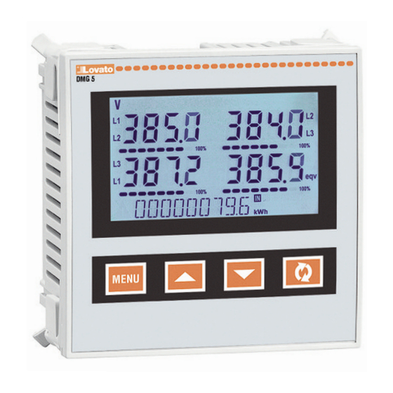
- Page 2 INTRODUCTION The DMG5... multimeters have been designed to combine the maximum possible easiness of operation together with a wide choice of advanced functions. The flush-mount 96x96mm housing joins the modern design of the front panel with the tool-less mounting of the device body. The backlighted LCD display offers a user-friendly interface. DMG510 is also provided with a isolated RS485 interface with Modbus protocol to consent remote supervision.
-
Page 3: Wiring Test
WIRING TEST – The wiring test allows to verify if the connection of the DMG5... device has been executed properly. – To be able to execute the test, the device must be connected to an active plant, with the following conditions: •... - Page 4 WIRING DIAGRAMS FOR DMG500-510 3-phase connection whit or without neutral 2-phase connection P01.07 = L1-L2-L3-N L1-L2-L3 P01.07 = L1-N-L2 TA/CT1 TA/CT1 TA/CT2 TA/CT2 TA/CT3 100...440VAC 100...440VAC 110...250VDC 110...250VDC V2 V3 V2 V3 -- - -- - AUX SUPPLY VOLTAGE CURRENT...
-
Page 5: Terminals Position
RS485 INTERFACE Max 1200m 120R 120R RS485 RS485 RS485 DMG5... n°31 DMG5... n°1 MASTER TERMINALS POSITION DMG500 DMG510 Aux supply Aux supply 100-240V~ 100-240V~ 50/60Hz 50/60Hz MECHANICAL DIMENSIONS AND FRONT PANEL CUTOUT (mm) -
Page 6: Technical Characteristics
TECHNICAL CHARACTERISTICS Supply dditional errors Rated voltage Us 100 - 240V~ Temperature 0.05%/°K per V, A, W 110 - 250V= Insulation Operating voltage range 90 - 264V~ Rated insulation voltage Ui 600V~ 93.5 - 300V= Rated impulse withstand voltage Uimp 9.5kV Frequency 45 - 66Hz... - Page 7 DMG500 - DMG510 W RNING! TTENZIONE! – Carefully read the manual before the installation or use. – Leggere attentamente il manuale prima dell’utilizzo e l’installazione. – This equipment is to be installed by qualified personnel, complying to current standards, to avoid –...
- Page 8 INTRODUZIONE I multimetri DMG5... sono stati progettati per unire la massima semplicità di utilizzo con una ampia scelta di funzioni avanzate. In esecuzione per montaggio a pannello con dimensioni standard 96x96mm, uniscono il moderno design del frontale alla praticità di montaggio. Il display retroilluminato LCD consente una interfaccia utente chiara ed intuitiva.
-
Page 9: Test Di Collegamento
TEST DI COLLEGAMENTO – Il test di collegamento consente di verificare se l’installazione del multimetro è stata effettuata correttamente. – Per poter eseguire il test, il multimetro deve essere inserito in un impianto attivo con le seguenti condizioni: • sistema trifase con presenza di tutte le fasi (V > 50VAC L-N) •... - Page 10 SCHEMI DI COLLEGAMENTO PER DMG500-510 Connessione trifase con o senza neutro Connessione bifase P01.07 = L1-L2-L3-N L1-L2-L3 P01.07 = L1-N-L2 TA/CT1 TA/CT1 TA/CT2 TA/CT2 TA/CT3 100...440VAC 100...440VAC 110...250VDC 110...250VDC V2 V3 V2 V3 -- - -- - AUX SUPPLY VOLTAGE...
-
Page 11: Disposizione Morsetti
INTERFACCIA RS485 Max 1200m 120R 120R RS485 RS485 RS485 DMG5... n°31 DMG5... n°1 MASTER DISPOSIZIONE MORSETTI DMG500 DMG510 Aux supply Aux supply 100-240V~ 100-240V~ 50/60Hz 50/60Hz DIMENSIONI MECCANICHE E FORATURA PANNELLO (mm) -
Page 12: Caratteristiche Tecniche
CARATTERISTICHE TECNICHE limentazione Errori addizionali Tensione nominale Us 100 - 240V~ Temperatura 0,05%/°K per V, A, W 110 - 250V= Isolamento Limiti di funzionamento 90 - 264V~ Tensione nominale d’isolamento Ui 600V~ 93,5 - 300V= Tensione nomi. di tenuta a impulso Uimp 9,5kV Frequenza 45 - 66Hz...
Need help?
Do you have a question about the DMG500 and is the answer not in the manual?
Questions and answers