Table of Contents
Advertisement
Quick Links
LOVATO ELECTRIC S.P.A.
24020 GORLE (BERGAMO) ITALIA
VIA DON E. MAZZA, 12
TEL. 035 4282111
FAX (Nazionale): 035 4282200
FAX (International): +39 035 4282400
L
E
E-mail info@
ovato
lectric.com
L
E
Web
www.
ovato
lectric.com
ATTENZIONE!!
WARNING!
– Leggere attentamente il manuale
– Carefully read the manual before the
prima dell'utilizzo e l'installazione.
– Questi apparecchi devono essere
– This equipment is to be installed by
installati da personale qualificato, nel
rispetto delle vigenti normative
impiantistiche, allo scopo di evitare
danni a persone o cose.
– Before any maintenance operation
– Prima di qualsiasi intervento sullo
strumento, togliere tensione dagli
ingressi di misura e di alimentazione
e cortocircuitare i trasformatori di
corrente.
– The manufacturer cannot be held
– Il costruttore non si assume
responsabilità in merito alla
sicurezza elettrica in caso di utilizzo
improprio del dispositivo.
– Products illustrated herein are
– I prodotti descritti in questo
documento sono suscettibili in
qualsiasi momento di evoluzioni o di
modifiche. Le descrizioni ed i dati a
catalogo non possono pertanto
avere alcun valore contrattuale.
– Un interruttore o disgiuntore va
compreso nell'impianto elettrico
dell'edificio. Esso deve trovarsi in
– A circuit breaker must be included in
stretta vicinanza dell'apparecchio ed
essere facilmente raggiungibile da
parte dell'operatore. Deve essere
marchiato come il dispositivo di
interruzione dell'apparecchio:
IEC/ EN 61010-1 § 6.11.3.1.
– Installare lo strumento in
contenitore e/o quadro elettrico con
– Fit the instrument in an enclosure or
grado di protezione minimo IP40.
– Pulire lo strumento con panno
morbido, non usare prodotti
– Clean the instrument with a soft dry
abrasivi, detergenti liquidi o solventi.
INDICE
Pag.
INDEX
Introduzione
2
Introduction
Descrizione
2
Description
Funzione dei tasti frontali
2
Keyboard functions
Visualizzazione delle misure
3
Measurement viewing
Navigazione fra le pagine
4
Display page navigation
del display
Table of display pages
Tabella delle pagine del display
5
Harmonic analysis page
Pagina analisi armonica
6
Waveform page
Pagina forme d'onda
6
Energy meters page
Pagina contatori di energia
7
Hour counters page
Pagina contaore
7
Trend graph page
Pagina grafico trend
8
Counters page
Pagina contatori
9
User pages
Pagine utente
9
Main menu
Menu principale
10
Password access
Accesso tramite password
11
Expandability
Espandibilità
12
Additional resources
Risorse aggiuntive
13
Communication channels
Canali di comunicazione
13
Data-logger function
Funzione data logger
13
Inputs, outputs, internal variables,
counters
ACHTUNG!!
– Das Handbuch vor der Installation
installation or use.
und Benutzung aufmerksam
durchlesen.
qualified personnel, complying to
– Diese Geräte müssen von
current standards, to avoid damages
qualifiziertem Personal und unter
or safety hazards.
Beachtung der gültigen
Installationsvorschriften installiert
on the device, remove all the
werden, um Personen- und
voltages from measuring and
Sachschäden zu vermeiden.
supply inputs and short-circuit the
– Vor der Durchführung von Arbeiten
CT input terminals.
am Gerät, die Spannung an den
Mess- und Versorgungseingängen
responsible for electrical safety in
unterbrechen und die Stromwandler
case of improper use of the
kurzschließen.
equipment.
– Der Hersteller übernimmt bei
unsachgemäßem Gebrauch des
subject to alteration and changes
Geräts keinerlei Haftung bezüglich
without prior notice. Technical data
der elektrischen Sicherheit.
and descriptions in the
– Die in diesem Handbuch
documentation are accurate, to the
beschriebenen Produkte können
best of our knowledge, but no
jederzeit weiterentwickelt werden
liabilities for errors, omissions or
oder Änderungen erfahren. Die
contingencies arising there from are
Beschreibungen und Daten im
accepted.
Katalog sind daher als unverbindlich
zu betrachten.
the electrical installation of the
– In die elektrische Anlage des
building. It must be installed close
Gebäudes ist ein Ausschalter oder
by the equipment and within easy
Trennschalter zu integrieren, der
reach of the operator. It must be
sich in der Nähe des Geräts befinden
marked as the disconnecting device
und von Seiten des Benutzers leicht
of the equipment:
erreichbar sein muss. Er muss als
IEC /EN 61010-1 § 6.11.3.1.
Trennvorrichtung für das Gerät
gekennzeichnet sein:
cabinet with minimum IP40 degree
IEC/EN 61010-1 § 6.11.3.1.
protection.
– Das Gerät in einem Gehäuse
und/oder in einer Schalttafel mit
cloth; do not use abrasives, liquid
Schutzart von mindestens IP40
detergents or solvents.
installieren.
– Das Gerät mit einem weichen
Lappen reinigen und keine
Scheuermittel, flüssigen
Reinigungsmittel oder Lösungsmittel
verwenden.
Page
INHALT
2
Einführung
2
Beschreibung
2
Tastenfunktionen
3
Anzeige der Messungen
4
Blättern in den Display-Seiten
5
Tabelle der Display-Seiten
6
Oberwellenanalyse-Seite
6
Wellenformen-Seite
7
Energiezähler-Seite
7
Stundenzähler-Seite
8
Trendgrafik-Seite
9
Zähler-Seite
9
Benutzerseiten
10
Hauptmenü
11
Passwort-Zugang
12
Erweiterbarkeit
13
Zusätzliche Ressourcen
13
Kommunikationskanäle
13
Datenlogger-Funktion
15
Eingänge, Ausgänge, interne
Variablen, Zähler
I
MULTIMETRO DIGITALE
GB
DIGITAL MULTIMETER
D
DIGITALMULTIMETER
F
MULTIMETRE NUMERIQUE
E
MULTÍMETRO DIGITAL
DMG300
ATTENTION !
– Lire attentivement le manuel avant
l'installation ou toute
l'utilisation.
– Ces appareils doivent être installés
par un personnel qualifié en
respectant les normes en vigueur
relatives aux installations pour éviter
tout risque pour le personnel et le
matériel.
– Avant toute intervention sur
l'appareil, couper ses entrées de
mesure et l'alimentation auxiliaire de
l'appareil et court-circuiter le
secondaire des transformateurs de
courant.
– Le fabricant ne peut être tenu
responsable de la sûreté électrique
en cas de mauvaise utilisation de
l'appareil.
– Les produits décrits dans cette
publication peuvent à tout moment
être susceptibles d'évolutions ou de
modifications. Les descriptions et
les données y figurant ne peuvent en
conséquence revêtir aucune valeur
contractuelle.
– Dans l'installation électrique de
l'édifice, il faut prévoir un
interrupteur magnétothermique,
situé à proximité de l'appareil et
d'accès facile. Il doit être marqué
comme le dispositif de
sectionnement de l'appareil :
IEC/EN 61010-1§6.11.3.1.
– L'appareil va installer dans un coffret
et/ou un tableau électrique ayant un
degré de protection minimum IP40.
– Nettoyer l'appareil avec un tissu
propre et ne pas employer les
produits abrasifs, les détergents
liquides ou les dissolvants.
Pag.
SOMMAIRE
2
Introduction
2
Description
2
Fonction des touches frontales
3
Visualisation des mesures
4
Navigation sur pages de l'afficheur
5
Table des pages de l'afficheur
6
Page analyse harmoniques
6
Page forme d'onde
7
Page compteurs d'énergie
7
Page compteur horaire
8
Page graphe de tendance
9
Page compteurs
9
Pages utilisateur
10
Menu principal
11
Accès par mot de passe
12
Extensibilité
13
Ressources additives
13
Voie de communication
13
Fonction d'enregistreur de données 13
15
Entrées, sorties, variables internes, 15
compteurs
¡ATENCIÓN!
– Leer detenidamente el manual antes
del uso y la instalación.
– Estos aparatos deben ser instalados
por personal cualificado y de
conformidad con las normativas
vigentes en materia de equipos de
instalación a fin de evitar daños
personales o materiales.
Antes de efectuar cualquier
intervención en el instrumento,
desconectar la tensión en las
entradas de medición y alimentación
y cortocircuitar los transformadores
de corriente.
– El fabricante declina cualquier
responsabilidad relacionada a la
seguridad eléctrica en caso de uso
impropio del dispositivo.
– Los productos descritos en este
documento pueden ser modificados
o perfeccionados en cualquier
momento. Por tanto, las
descripciones y los datos aquí
indicados no implican algún vínculo
contractual.
– La instalación eléctrica del edificio
debe contar con un interruptor o
disyuntor. Éste debe estar colocado
muy cerca del aparato, en una
ubicación de fácil acceso para el
operador. Debe estar marcado como
dispositivo de interrupción del
aparato: IEC/EN 61010-1 § 6.11.3.1.
– Instalar el instrumento en una caja
y/o cuadro eléctrico con grado de
protección mínimo IP40.
– Limpiar el instrumento con un paño
suave, evitando el uso de productos
abrasivos, detergentes líquidos o
disolventes
Page
INDICE
Pag.
2
Introducción
2
Descripción
2
Función de las teclas frontales
3
Visualización de las medidas
4
Navegación entre las páginas
de la pantalla
5
Tabla de las páginas de la pantalla
6
Página análisis armónico
6
Página formas de onda
7
Página contadores de energía
7
Página cuentahoras
8
Página gráfico trend
9
Página Contadores
9
Páginas usuario
10
Menú principal
11
Acceso con contraseña
12
Expandibilidad
13
Recursos adicionales
13
Canales de comunicación
Función registro de datos
2
2
2
3
4
5
6
6
7
7
8
9
9
10
11
12
13
13
13
1
Advertisement
Table of Contents

Related Manuals for Lovato DMG300


Summary of Contents for Lovato DMG300
- Page 1 MULTIMETRO DIGITALE DIGITAL MULTIMETER DIGITALMULTIMETER LOVATO ELECTRIC S.P.A. 24020 GORLE (BERGAMO) ITALIA MULTIMETRE NUMERIQUE VIA DON E. MAZZA, 12 TEL. 035 4282111 MULTÍMETRO DIGITAL FAX (Nazionale): 035 4282200 FAX (International): +39 035 4282400 DMG300 E-mail info@ ovato lectric.com www. ovato lectric.com...
-
Page 2: Beschreibung
INTRODUCTION INTRODUCCIÓN Il multimetro DMG300 è stato The DMG300 multimeter has been Das Multimeter DMG300 wurde Le multimètre DMG300 est conçu pour El multímetro DMG300 ha sido progettato per unire la massima designed to combine the maximum entwickelt, um höchste unir la facilité... -
Page 3: Anzeige Der Messungen
VISUALIZZAZIONE DELLE MISURE VIEWING OF MEASUREMENTS ANZEIGE DER MESSUNGEN VISUALISATION DES MESURES VISUALIZACIÓN DE LAS MEDIDAS – I tasti L e M consentono di – The L and M keys allow to scroll – Mit Hilfe der Tasten L uns M –... -
Page 4: Blättern In Den Display-Seiten
Esempio di pagina Barre grafiche Example of display page with Beispiel für Seite mit Balkengrafik Exemple de page graphique à barres Ejemplo de página con Gráficos de bar-graphs Barras 1 - Unità di misura 3 - Indicazione fasi Unit of measure Phase indication Maßeinheit Angabe der Phase... -
Page 5: Del Display Table Of Display
TABELLA DELLE PAGINE DEL DISPLAY TABLE OF DISPLAY PAGES TABELLE DER DISPLAY-SEITEN TABLE DES PAGES DE L’AFFICHEUR TABLA DE LAS PÁGINAS DE LA PANTALLA Selezione con L e M Selezione con Selection with L and M Selection with Auswahl mit L und M Auswahl mit Selection avec L et M Selection avec... -
Page 6: Oberwellenanalyse-Seite
– The DMG300 provides the harmonic – Das DMG300 erlaubt die – Le DMG300 fournit l’analyse – En DMG300 puede verse el análisis armonica fino al 31.mo ordine delle analysis up to the 31st order of the Oberwellenanalyse bis zur harmonique jusqu’au rang 31éme... -
Page 7: Energiezähler-Seite
PAGINA CONTATORI DI ENERGIA ENERGY METERS PAGE ENERGIEZÄHLER-SEITE PAGE COMPUTEURS D’ÉNERGIE PÁGINA CONTADORES DE ENERGÍA – Nella pagina contatori di energia – The Energy meters page shows the – Auf der Energiezähler-Seite wird – La page des computeurs d’énergie – En la página de los contadores de vengono visualizzati following meters simultaneously: gleichzeitig folgendes angezeigt:... -
Page 8: Trendgrafik-Seite
PAGINA GRAFICO TREND TREND GRAPH PAGE TRENDGRAFIK-SEITE PAGE GRAPHE DE TENDANCE PÁGINA GRÁFICO TREND – La pagina trend consente di – The trend graph page allows to – Die Trendgrafik-Seite gestattet, eine – La page du graphe de tendance – La página Trend permite visualizar visualizzare un grafico con show the changes in the time Grafik mit dem zeitlichen Verlauf... -
Page 9: Zähler-Seite
Messungen enthalten, die unter den afficher 4 mesures, librement parámetros cada una, seleccionados fra quelle disponibili sul DMG300. DMG300. auf DMG300 verfügbaren choisies parmi les mesures libremente entre los disponibles en –... -
Page 10: Hauptmenü
MENU PRINCIPALE MAIN MENU HAUPTMENÜ MENU PRINCIPAL MENÚ PRINCIPAL – Il menu principale è costituito da un – The main menu is made up of a – Das Hauptmenü besteht aus einer – Le menu principal comprend des – El menú principal consta de un insieme di icone grafiche che group of graphic icons (shortcuts) Gruppe graphischer Icons, die den... -
Page 11: Passwort-Zugang
ACCESSO TRAMITE PASSWORD PASSWORD ACCESS PASSWORT-ZUGANG ACCÉS PAR MOT DE PASSE ACCESO CON CONTRASEÑA – La password serve per abilitare o – The password is used to enable or – Das Passwort dient dazu, den – Le mot de passe est utilisé pour –... -
Page 12: Erweiterbarkeit
– Die Steckreihenfolge der Module ist frei wählbar. – Quando un DMG300 viene – When a DMG300 is powered up, it – Beim Einschalten der – Quand un DMG300 est mise sous – Cuando un DMG300 recibe alimentato, riconosce... -
Page 13: Zusätzliche Ressourcen
COMMUNICATION CHANNELS KOMMUNIKATIONSKANÄLE VOIE DE COMMUNICATION CANALES DE COMUNICACIÓN – Al DMG300 è possibile connettere al – The DMG300 supports a maximum – An das DMG300 können maximal 2 – Le DMG300 supporte un maximum – En DMG300 puede conectarse un... - Page 14 dati sotto forma di tabella di – The data logger allows to store at die Bedingungen für die Aufzeichnung Xpress, qui permet de choisir les datos en forma de tabla MicroSoft- ® ® database Microsoft-Access regular intervals up to 32 variables zu wählen sowie die Daten in Form variables et les modalités Access...
-
Page 15: Eingänge, Ausgänge, Interne
INP1...8 and während die folgenden Eingänge suite. mientras que los siguientes – Per il DMG300 sono previsti un OUT1...8. For every I/O, there is a nach rechts INP2, INP3 etc. lauten – Le DMG300 supporte un maximum prosiguiendo hacia la derecha serán... - Page 16 SOGLIE LIMITE (LIM) LIMIT THRESHOLDS (LIM) SCHWELLENGRENZWERTE (LIM) SEUILS DE LIMITE (LIM) VALORES DE UMBRAL (LIM) – Le soglie limite LIMn sono delle – The LIMn thresholds are internal – Die Schwellengrenzwerte LIMn sind – Les seuils de limite LIMn sont –...
- Page 17 – Das DMG300 bietet die Möglichkeit, (REM) – DMG300 puede aceptar hasta un gestire un massimo di 8 variabili – The DMG300 can manage up to 8 maximal 8 Remote-Variablen – Le DMG300 peut gérer jusqu’à 8 máximo de 8 variables controladas...
- Page 18 ALLARMI (ALA) ALARMS (ALA) ALARME (ALA) ALARMES (ALA) ALARMAS (ALA) – L’utente ha la possibilità di definire – The user has the possibility to define – Der Benutzer hat die Möglichkeit, – L’utilisateur a la possibilité de définir – El usuario tiene la posibilidad de un massimo di 8 allarmi a maximum of 8 programmable maximal 8 programmierbare Alarme...
- Page 19 TARIFE TARIFICATION TARIFAS – Per il conteggio dell’energia, il – For the energy billing, the DMG300 – Zum Zwecke der Energiezählung – Pour le comptage de l’énergie, le – Para contar la energía, DMG300 DMG300 ha la possibilità di gestire can manage 4 different tariffs in bietet das DMG300 die Möglichkeit,...
- Page 20 – Nella seguente tabella sono elencati i – The following table lists the available – In der folgenden Tabelle sind die zur – La table suivante indique la liste des – En la siguiente tabla pueden verse sottomenu disponibili sub-menus: Verfügung stehenden Untermenüs sous-menu disponibles.
- Page 21 – Selezionare il sottomenu e premere – Das Untermenü auswählen und die – Sélectionnez le sous-menu et – Seleccionar el submenú y pulsar la – Select the sub-menu and press il tasto per visualizzare i Taste drücken, damit die appuyez sur la touche pour tecla para visualizar los...
- Page 22 TABELLA PARAMETRI PARAMETER TABLE PARAMETERTABELLE TABLE DES PARAMETRES TABLA DE PARÁMETROS M01 - GENERALE / GENERAL / ALLGEMEIN / GENERAL / GENERAL Default Range P01.01 Primario TA 5-10000 CT primary Primärspule Stromwandler Primarie TC Primario TC P01.02 Secondario TA CT secondary Sekundärspule Stromwandler Secondaire TC Secundario TC...
- Page 23 M02 - UTILITA’ / UTILITY / UTILITY / UTILITE / UTILIDADES Default Range P02.01 Lingua English English Language Italiano Sprache Francais Langue Espanol Idioma Portoguese P02.02 Contrasto LCD 0-100 Display contrast LCD-Kontrast Contraste afficheur Contraste LCD P02.03 Intensità retroilluminazione display alta 0-100 High backlight level Hohe Helligkeit Hintergrundbeleuchtung Display...
- Page 24 M04 - INTEGRAZIONE / INTEGRATION / INTEGRATION / INTEGRATION / INTEGRACIÓN Default Range P04.01 Modo integrazione Scorr. Fisso / Scorrevole Integration mode Sincronismo / Bus Integrationsmodus Shift Fixed / Shift Mode d’intégration Sync. / Bus Modo integración Gleitend Fest / Gleitend Synchr.
- Page 25 M05 - CONTAORE / HOUR METER / STUNDENZÄHLER / COMPTEUR HORAIRE / CUENTAHORAS Default Range P05.01 Abilitazione generale contaore OFF-ON General hour meter enable Allgemeine Aktivierung Stundenzähler Activation générale compteur horaire Habilitación general cuentahoras P05.02 Abilitazione contaore parziale OFF-ON- INPx- Partial hour meter enable LIMx-BOOx Aktivierung Servicestundenzähler...
- Page 26 M07 - COMUNICAZIONE / COMMUNICATION / KOMMUNIKATION / COMMUNICATION / COMUNICACIÓN Default Range P07.n.01 Indirizzo seriale nodo 01-255 Serial node address Serielle Adresse Knoten Adresse série noeud Dirección serial nudo P07.n.02 Velocità seriale 38400 1200 Serial speed 2400 Serielle Geschwindigkeit 4800 Vitesse série 9600...
- Page 27 P07.n.06, P07.n.07, P07.n.08, P07.n.06, P07.n.07, P07.n.08, P07.n.06, P07.n.07, P07.n.08 – TCP- P07.n.06, P07.n.07, P07.n.08, P07.n.06, P07.n.07, P07.n.08, P07.n.13 – Coordinate TCP-IP per P07.n.13 –TCP-IP coordinates for IP Koordinaten für Applikationen mit P07.n.13 – Coordonnées TCP-IP pour P07.n.13 – Coordenadas TCP-IP para applicazioni con interfaccia Ethernet.
- Page 28 P08.n.02 - Definisce il funzionamento P08.n.02 - Function of the limit P08.n.02 - Definiert die Funktion des P08.n.02 - définit le fonctionnement du P08.n.02 - Determina el della soglia limite. Può essere: threshold. It can be: Schwellengrenzwerts. Kann folgende seuil de limite. Il peut être : funcionamiento del valor de umbral.
- Page 29 M10 - CONTATORI / COUNTERS / ZÄHLER / COMPTEURS / CONTADORES Default Range P10.n.01 Sorgente conteggio OFF-ON-INPx-LIMx-BOOx Count source Zählungsauslösung Source comptage Fuente cálculo P10.n.02 Numero canale (x) Channel number (x) Nummer Kanal (x) Numéro de voie (x) Número canal (X) P10.n.03 Moltiplicatore 1-1000 Multiplier...
- Page 30 M11 - IMPULSI / PULSES / IMPULSE / IMPULSIONS / PULSOS Default Range P11.n.01 Misura sorgente kWh+ kWh+,kWh-,kvarh+,kvarh-,kVAh Source measurement Referenzmessung Mesure de source Medida fuente P11.n.02 Unità di conteggio 10/100/1k/10k Count unit Einheit der Zählung Unité de comptage Unidad de medida P11.n.03 Durata impulso 0.01-1.00 Pulse duration...
- Page 31 Nota: questo menu è diviso in 8 sezioni, Note: This menu is divided into 8 Hinweis: Dieses Menü ist in 8 Nota : ce menu est repartisè en 8 Nota: Este menú se subdivide en 8 per le variabili Booleane BOO1..8 sections, for Boolean variables BOO1..8 Abschnitte unterteilt, für die Booleschen sections, pour les variables booléanes...
- Page 32 P14.n.01 = Funzione della uscita: P14.n.01 = Function of the output: P14.n.01 = Funktion des Ausgangs: P14.n.01 = fonction de la sortie : P14.n.01 = Función de la salida: OFF - Uscita disabilitata OFF - Output disabled OFF - Ausgang deaktiviert OFF - sortie désactivée OFF - Salida inhabilitada ON - Uscita sempre abilitata...
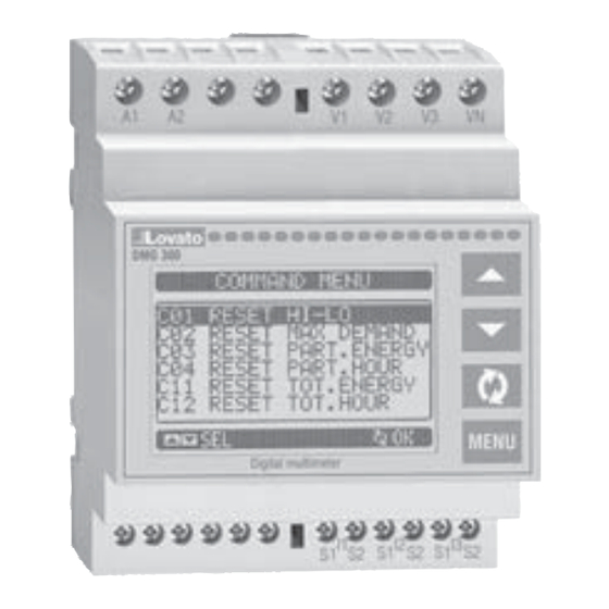
- Page 33 Cod. COMANDO LIVELLO ACCESSO DESCRIZIONE Code COMMAND ACCESS LEVEL DESCRIPTION Code BEFEHL ZUGANGS-EBENE BESCHREIBUNG Code COMMANDE NIVEAU ACCES DESCRIPTION Cód. MANDO NIVEL ACCESO DESCRIPCIÓN Utente Avanzato User Advanced Benutzer Erweitert Utilisateur Avancé Usuario Avanzado C.01 RESET HI-LO Azzera i valori di picco HI e LO di tutte le misure RESET HI-LO Reset of HI and LO peaks of all readings HI-LO RESET...
- Page 34 – Una volta selezionato il comando – Once the required command has – Nach der Auswahl des gewünschten – Après avoir sélectionné la – Una vez seleccionado el mando desiderato, premere been selected, press to execute Befehls drücken, damit dieser commande nécessaire, appuyez sur deseado, pulsar para ejecutarlo.
- Page 35 CARATTERISTICHE TECNICHE Alimentazione ausiliaria Isolamento Tensione nominale Us 100...240V Tensione nominale d’isolamento Ui 690V 110...250V Tensione nominale di tenuta a impulso Uimp 9,5kV Limiti di funzionamento 85...264V Tensione di tenuta a frequenza d’esercizio 5,2kV 93,5...300V Connessioni circuito alimentazione/misura tensioni Frequenza 45...66Hz Tipo di morsetti A vite (fissi)
- Page 36 TECHNICAL CHARACTERISTICS Auxiliary supply Insulation Rated voltage Us 100...240V Rated insulation voltage Ui 690V 110...250V Rated impulse withstand voltage Uimp 9.5kV Operating voltage range 85...264V Power frequency withstand voltage 5.2kV 93.5...300V Auxiliary supply and voltage input connections Frequency range 45...66Hz Type of terminal Screw (fixed) Power consumption/dissipation...
- Page 37 TECHNISCHE EIGENSCHAFTEN Hilfsversorgung Isolationsspannung Nennspannung Us 100...240V Nennisolationsspannung Ui 690V 110...250V Nennhaltespannung mit Impuls Uimp 9,5kV Betriebsbereich 85...264V Haltespannung bei Betriebsfrequenz 5,2kV 93,5...300V Anschlüsse Versorgung/Spannungsmessung Frequenz 45...66Hz Klemmentyp Mit Schraube (fest) Leistungsaufnahme/Leistungsverlust 3,2VA 1,3W Anzahl der Klemmen 4 für Spannungsüberwachung ≥50ms Sicherheit bei Kurzunterbrechungen 2 für Versorgung...
- Page 38 CARACTERISTIQUES TECHNIQUES Alimentation auxiliaire Isolation Tension assignée Us 100...240V Tension assignée d’isolement Ui 690V 110...250V Tension assignée de tenue aux chocs Uimp 9,5kV Limites de fonctionnement 85...264V Tension de tenue à fréquence de service 5,2kV 93,5...300V Connexions circuit alimentation auxiliaire et entrées de tension Fréquence 45...66Hz Type de borne...
- Page 39 CARACTERÍSTICAS TÉCNICAS Alimentación auxiliar Aislamiento Tensión nominal Us 100...240V Tensión nominal de aislamiento Ui 690V 110...250V Tensión nominal de retención por impulso Uimp 9,5kV Límites de funcionamiento 85...264V Tensión de retención a frecuencia 5,2kV 93,5...300V de empleo Frecuencia 45...66Hz Conexiones circuito alimentación/medida tensiones Potencia absorbida/disipada 3,2VA 1,3W Tipo de terminales...
- Page 40 SCHEMI DI CONNESSIONE WIRING DIAGRAMS ANSCHLUSSPLÄNE SCHEMAS DE CONNEXION ESQUEMAS DE CONEXIÓN Connessione trifase con o senza neutro Connessione bifase 3-phase connection with or without neutral 2-phase connection 3-phasiger Anschluss mit oder ohne Nullleiter 2-phasiger Anschluss Connexion triphasée avec ou sans le neutre Connexion biphasée Conexión trifásica con o sin neutro Conexión bifásica...
Need help?
Do you have a question about the DMG300 and is the answer not in the manual?
Questions and answers