Table of Contents
Advertisement
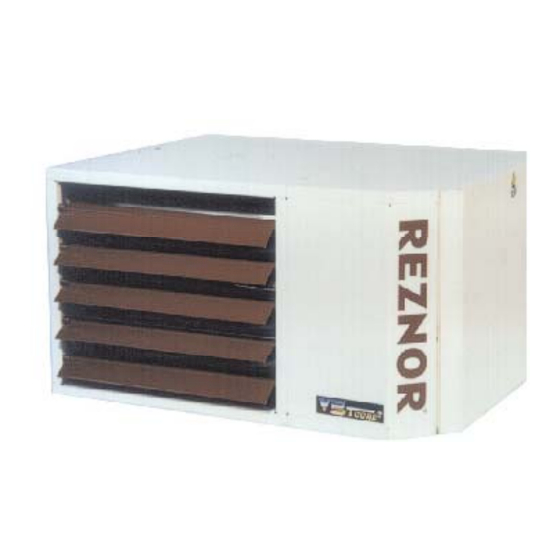
Gas fi red Balanced fl ue / Fan assisted fl ue
B
elarus, Bulgaria,
F
G
inland,
reece,
N
P
orway,
Please read this document carefully before commencing installation, commissioning and/or servicing.
Leave it with the user or attached to the appliance or gas service meter after installation.
Improper installation, adjustment, alteration, service or maintenance can cause property damage, injury or death.
All work must be carried out by appropriately qualifi ed persons.
The manufacturer does not take any responsibility in the event of non-observance of the regulations concerning
the connection of the apparatus causing an evil operation possibly resulting in damage to the apparatus and/or
environment in which the unit is installed.
Subject to modifi cations
UDSA 008-2 / 100-2
unit heater
INSTALLATION
COMMISSIONING
SERVICING
Applies to
C
C
hina,
zech Republic,
H
I
ungary,
celand,
P
R
oland,
ortugal,
omania,
S
S
lovenia,
pain,
These appliances meet the following EC Directives:
DIR 2009/142/EC:GAD
DIR 2004/108/EC :EMC
DIR 2006/95/EC :LVD
DIR 2006/42/EC :MD
C
C
roatia,
yprus,
L
L
M
atvia,
ithuania,
ontenegro,
R
ussian Federation,
S
T
U
weden,
urkey,
kraine
WARNING
Reznor Menen - J.&M. Sabbestraat 130/A000, B 8930 Menen
Tel.: +32 56/52 95 11 · Fax +32 56/52 95 33
1103UDSA-2--EN
D
E
enmark,
stonia,
N
ew Zealand,
S
S
erbia,
lovakia,
1103UDSA-2--EN, Pag. 1/36
Advertisement
Table of Contents
Troubleshooting


Need help?
Do you have a question about the UDSA 008-2 and is the answer not in the manual?
Questions and answers