Download Print this page
Reznor UDXC Installation, Operation And Maintenance Manual

Reznor UDXC Installation, Operation And Maintenance Manual

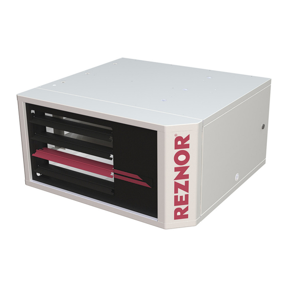
Gas-fired unit heater

Advertisement

Quick Links

GAS-FIRED UNIT HEATER INSTALLATION, OPERATION,
AND MAINTENANCE
• Failure to follow safety warnings exactly could result in serious injury, death, or property
damage.
• Improper installation, adjustment, alteration, service, or maintenance can cause serious injury,
death, or property damage.
• Installation and service must be performed by a qualified installer, service agency, or the
gas supplier.
• Be sure to read and understand the installation, operation, and service instructions in this
manual.
• Do not store or use gasoline or other flammable vapors and liquids in the vicinity of this or
any other appliance.
• Do not try to light any appliance.
• Do not touch any electrical switch; do not use any phone in your building.
• Leave the building immediately.
• Immediately call your gas supplier from a phone remote from the building. Follow the gas
supplier's instructions.
• If you cannot reach your gas supplier, call the fire department.
DO NOT DESTROY. PLEASE READ CAREFULLY. KEEP IN A SAFE PLACE FOR FUTURE REFERENCE.
MODELS UBXC AND UDXC
 ⚠ DANGER ⚠ 
FIRE OR EXPLOSION HAZARD
WHAT TO DO IF YOU SMELL GAS
Revision: UBXC-UDXC-IOM (02-24) 1042980-0
Supersedes: — (Original Version)

Advertisement

loading
Need help?

Need help?

Do you have a question about the UDXC and is the answer not in the manual?

Questions and answers

Subscribe to Our Youtube Channel

Summary of Contents for Reznor UDXC

  • Page 1 Revision: UBXC-UDXC-IOM (02-24) 1042980-0 Supersedes: — (Original Version) GAS-FIRED UNIT HEATER INSTALLATION, OPERATION, AND MAINTENANCE MODELS UBXC AND UDXC  ⚠ DANGER ⚠  FIRE OR EXPLOSION HAZARD • Failure to follow safety warnings exactly could result in serious injury, death, or property damage.
  • Page 2: Table Of Contents

    Suspension of Heater Using Option CK22 Hanger Kit (Model UDXC, Unit Sizes 30–125) . . . . . . . . . . . . . .
  • Page 3 Flame Rollout Switch Maintenance (Model UDXC, Unit Sizes 30–125) . . . . . . . . . . . . . . . .
  • Page 4: General Information

    • Children should be supervised to ensure that they do not play with the appliance. ⚠ CAUTION ⚠ To prevent damage to the unit or to its internal components, it is recommended that two wrenches be used when loosening or tightening nuts. Do not overtighten! UBXC-UDXC-IOM (02-24) 1042980-0...
  • Page 5: Warranty

    • These unit heaters are listed by Intertek for use in industrial and commercial installations in the United States and Canada . In addition, model UDXC in unit sizes 30, 45, 60, 75, 100, and 125 is listed in the United States and Canada as a utility heater for use in non-living spaces that are attached to, adjacent to, or part of a structure that contains space for family living quarters .
  • Page 6: Heater Location

    . The louver angles listed are relative to the top of the heater . The throw pattern changes with the addition of optional vertical louvers and/or downturn nozzles . UBXC-UDXC-IOM (02-24) 1042980-0...
  • Page 7 11 (3 .4) 22 (6 .7) 21 (6 .4) 18 (5 .5) 17 (5 .2) 18 (5 .5) — 53 (16 .2) 50 (15 .2) 51 (15 .5) 40 (12 .2) Downward louver angle 52° 52° 56° 57° Figure UBXC-UDXC-IOM (02-24) 1042980-0...
  • Page 8 34 (10 .4) 10 (3 .0) 44 (13 .4) 78 (23 .8) 100 (30 .5) 94 (28 .7) 106 (32 .3) 109 (33 .2) 104 (31 .7) Downward louver angle 39° 24° 23° 20° 21° 17° 24° Figure UBXC-UDXC-IOM (02-24) 1042980-0...
  • Page 9 76 (23 .2) Downward louver angle 53° 49° 53° 45° 14 (4 .3) 16 (4 .9) 21 (6 .4) 24 (7 .3) 18 (5 .5) — — 64 (19 .5) 69 (21 .0) Downward louver angle 56° 50° Figure UBXC-UDXC-IOM (02-24) 1042980-0...
  • Page 10 48 (14 .6) 14 (4 .3) 137 (41 .8) 150 (45 .7) 160 (48 .8) 191 (58 .2) 137 (41 .8) 162 (49 .4) 162 (49 .4) Downward louver angle 25° 23° 25° 22° 28° 24° 23° Figure UBXC-UDXC-IOM (02-24) 1042980-0...
  • Page 11 156 (47 .5) Downward louver angle 32° 29° 32° 28° 34° 29° 29° Figure Table 3. Heater Throw Distance (Model UDXC) Unit Size (MBTUh) (Feet Distance or Angle (Meters)) Feet (Meters) 6 (1 .8) 7 (2 .1) 8 (2 .4) 9 (2 .7)
  • Page 12: Mounting Height Requirements

    GENERAL INFORMATION—CONTINUED Heater Location—Continued Heater Throw Distances with Standard Horizontal Louvers—Continued Table 3. Heater Throw Distance (Model UDXC) —Continued Unit Size (MBTUh) (Feet Distance or Angle (Meters)) Feet (Meters) 15 (4 .6) 16 (4 .9) 14 (4 .3) 16 (4 .9) 15 (4 .6)
  • Page 13: Dimensions

    HANGER BAR 2-1/2 FRONT VIEW SIDE VIEW (DIRECT-DRIVE BLOWER, UNIT SIZES 30–75) COMBUSTION VENT CONNECTION AIR INLET THERMOSTAT CONNECTION ELECTRIC GAS CONNECTION SUPPLY CONNECTION REAR VIEW BELT-DRIVE BLOWER (UNIT SIZES 150–400) Figure 2. Dimensions—Model UBXC (Refer to Table UBXC-UDXC-IOM (02-24) 1042980-0...
  • Page 14: Top View

    GENERAL INFORMATION—CONTINUED Dimensions—Continued COMBUSTION AIR INLET VENT CONNECTION THERMOSTAT CONNECTION ELECTRIC GAS CONNECTION SUPPLY CONNECTION TOP VIEW REAR VIEW FRONT VIEW SIDE VIEW Figure 3. Dimensions—Model UDXC (Refer to Table UBXC-UDXC-IOM (02-24) 1042980-0...
  • Page 15 42 (1067) 2-15/16 4-1/4 4-5/16 4-1/2 UDXC (75) (108) (110) (114) Varies with motor selection and belt adjustment for unit sizes 150–400 . Heater suspension points (3/8-16 FEM) . Heater suspension points for two-point suspension (3/8-16 FEM) . UBXC-UDXC-IOM (02-24) 1042980-0...
  • Page 16: Weights

    NOTE: For further details on supplying combustion air to a confined space, refer to the National Fuel Gas Code (ANSI Z223.1a, latest edition). CONFINED SPACE Figure 4. Confined Space Combustion Air Openings (Refer to Table UBXC-UDXC-IOM (02-24) 1042980-0...
  • Page 17: Installation

    . Table 7) that need to be assembled/installed prior ‰ Check to see if there are any field-installed options (refer to to unit installation . Ensure that all options ordered are at the installation site . UBXC-UDXC-IOM (02-24) 1042980-0...
  • Page 18: Heater Suspension

    MUST be plugged. • When the heater is lifted for suspension, support the bottom of the heater with plywood or other appropriately placed material. If the bottom is not supported, damage could occur. UBXC-UDXC-IOM (02-24) 1042980-0...
  • Page 19: Suspension Of Heater Using Option Ck8 Or Ck10 Hanger Kit

    The ceiling suspension kit (option CK22) allows the heater to be installed 1 inch from the ceiling without hanger rods . The ceiling suspension kit is used only on model UDXC unit sizes 30–125 . Refer to the installation instructions provided with the kit .
  • Page 20: Piping Connections

    (refer to the National Fuel Gas Code for additional information) . Table 8. Gas Supply Line Sizes Diameter of Pipe (Inches) Length 1-1/4 1-1/2 of Pipe (Feet) Cubic Feet per Hour 1100 2100 1281 1650 1007 1450 1270 1105 1050 UBXC-UDXC-IOM (02-24) 1042980-0...
  • Page 21: Supply Piping Connections

    • Do not intermix different vent system parts from different manufacturers in the same venting system. NOTE: Venting must be in accordance with local codes and with the National Fuel Gas Code (ANSI Z223.1) or the Installation Code for Gas Burning Appliances and Equipment (CSA B149.1). Local requirements supersede national requirements. UBXC-UDXC-IOM (02-24) 1042980-0...
  • Page 22: Condensation Mitigation

    • Double-wall Type B vent pipe: join pipe sections in accordance with the pipe manufacturer’s requirement—refer Figure 8 to the illustrated instructions in to connect double-wall pipe to the heater collar, single-wall pipe, and vent cap . Work quickly to assemble components before sealant dries . UBXC-UDXC-IOM (02-24) 1042980-0...
  • Page 23 Drill three small holes through the pipe and into collar venter outlet collar. spaced equally around pipe below sealant ring. Secure joint using 3/4-inch-long sheet metal screws. Do not overtighten screws. Figure 8. Instructions for Connecting Double-Wall Type B Vent Pipe to Single-Wall Pipe UBXC-UDXC-IOM (02-24) 1042980-0...
  • Page 24: Vent Terminal Requirements

    2 feet above the highest point where it passes through a roof of a building and at least 2 feet higher than any portion of a building within a horizontal distance of 10 feet (refer to Table 10) . UBXC-UDXC-IOM (02-24) 1042980-0...
  • Page 25 7 (2 .1) above Grade (ground level) 3 (0 .9) above Does not apply to the inlet of a direct vent appliance . Do not terminate the vent directly above a gas meter or service regulator . UBXC-UDXC-IOM (02-24) 1042980-0...
  • Page 26: Vent Connections For Standard Units

    The method of installation varies depending on the installation type: Category III venting (most installations) or Figure 10 Category I, commercial/industrial or residential locations, and vent configuration—common or not . See to determine the installation type and refer to the following subparagraphs for instructions . (standard 30-125 only) Figure 10. Installation Flowchart UBXC-UDXC-IOM (02-24) 1042980-0...
  • Page 27: Venter (Flue) Outlet Diameter

    2 .5 (0 .8) 6- to 7-inch (152- to 178-mm) enlarger Add all straight sections and equivalent lengths for elbows—the total combined length must not exceed the maximum vent length . Field-supplied taper-type connection required at the venter outlet . UBXC-UDXC-IOM (02-24) 1042980-0...
  • Page 28 SVE and SVEII 3 and 4 SVEIII 2, 3, and 4 Z-FLEX US Inc . SVEIV single-wall and SVEIV double-wall 4, 5, and 6 NovaVent single-wall and NovaVent double-wall Z-VentBlu single-wall and Z-VentBlu double-wall 3, 4, and 5 UBXC-UDXC-IOM (02-24) 1042980-0...
  • Page 29: Category Iii Commercial/Industrial Installations

    . Ensure that vent terminal is installed in accordance with section . Reznor (option CC1) Category III vent pipe or approved Category III vent cap (Note positions (shaded areas) of vent cap openings.) Figure 11. Horizontal Vent Terminal (Commercial/Industrial Installations) UBXC-UDXC-IOM (02-24) 1042980-0...
  • Page 30: Category Iii Residential Installations (Model Udxc)

    Category III Residential Installations (Model UDXC) Residential installations of model UDXC unit sizes 30–100 may use a Category III dedicated vent as defined by the National Fuel Gas Code (ANSI Z223 .1) or the Installation Code for Gas Burning Appliances and Equipment (CSA B149 .1) .
  • Page 31: Category I Venting

    Category III vent cap Figure 14. Vertical Vent Terminal (Residential Installations) Category I Venting Category I venting is used for some model UDXC units with either a dedicated vent or a common (with another appliance) vent . UBXC-UDXC-IOM (02-24) 1042980-0...
  • Page 32: Category I Commercial/Industrial Or Residential (Model Udxc) Installations With Vertical Dedicated Vent

    I common venting. Failure to comply may result in severe injury, death, and/or property damage. Residential installations of model UDXC unit sizes 30–100 may use a Category I common vent . Common venting is when two or more Category I appliances are vented into a single vertical vent . Install the vent as follows: Figure 15) .
  • Page 33 7 (178) One fan-assisted 5 (127) appliance and one 6 (152) non-fan-assisted appliance 7 (178) Type B double-wall vent pipe . Non-fan-assisted appliances rely solely on the natural buoyancy of the vent gases for venting . UBXC-UDXC-IOM (02-24) 1042980-0...
  • Page 34: Category I Residential Installations With Dedicated Vent (Model Udxc)

    National Fuel Gas Code . Category I Residential Installations with Dedicated Vent (Model UDXC) Residential installations of model UDXC unit sizes 30–100 may use a Category I dedicated vent . Install the vent as follows: Figure 16) .
  • Page 35: Electrical Connections

    • A two-stage valve circuit is NOT available on all models. • If the installation requires a stepdown transformer, follow the instructions shipped with the option package for installing the transformer . • All units have a built-in disconnect switch (see Figure 17) . UBXC-UDXC-IOM (02-24) 1042980-0...
  • Page 36: Supply Wiring Connection

    . The circuit board is factory-wired, but it is advisable to check to ensure that the black wire is the hot wire connected to terminal L1 and that the white wire is the neutral wire . Figure 18. Circuit Board (DSI Control Module) UBXC-UDXC-IOM (02-24) 1042980-0...
  • Page 37: Control Connections

    TROUBLESHOOTING section for probable causes and reset instructions for the following controls. FLAME ROLLOUT HIGH TEMPERATURE SWITCH PRESSURE SWITCH LIMIT SWITCH VENTER WHEEL AND MOTOR ASSEMBLY MOTOR COMBINATION GAS VALVE CIRCUIT BOARD Figure 20. Control Locations (Typical) UBXC-UDXC-IOM (02-24) 1042980-0...
  • Page 38: Pressure Switch

    Venter Wheel and Motor Assembly Figure 20) and operates to provide combustion airflow . The venter motor is assembled to the venter wheel (see Circuit Board (DSI Control Module) Operation is controlled by the circuit board (refer to section) . UBXC-UDXC-IOM (02-24) 1042980-0...
  • Page 39: Flame Rollout Switch (Model Udxc, Unit Sizes 30-125)

    If the manual-reset flame rollout switch activates, identify and correct the cause before resetting the switch. Never bypass the flame rollout switch; hazardous conditions could result. Unit sizes 30–125 of model UDXC are equipped with a temperature-activated, manually-reset flame rollout switch Figure 20) .
  • Page 40: Multiple Heater Control

    ‰ Check piping for leaks and proper gas line pressure and bleed trapped air from gas lines (refer to Supply Piping Connections section) . ‰ Check electrical wiring—ensure that all wire gauges are as recommended—service disconnect switch should be used—verify that fusing or circuit breakers are adequate for load use . UBXC-UDXC-IOM (02-24) 1042980-0...
  • Page 41: Startup

    11 . Burner flame is sensed and in 30 seconds after combination gas valve is energized, fan motor is energized . 12 . If flame is extinguished during main burner operation, integrated control system closes main valve and must be reset by interrupting power to control circuit (refer to lighting instructions provided with heater) . UBXC-UDXC-IOM (02-24) 1042980-0...
  • Page 42: To Turn Off Gas To Appliance

    Control deenergizes gas valve and proceeds to steps 6 and 7 removed 6 . Post-purge Venter motor remains on for 45-second post-purge period Thermostat is satisfied 7 . Fan/blower Fan/blower motor is deenergized after selected fan/blower OFF delay OFF delay UBXC-UDXC-IOM (02-24) 1042980-0...
  • Page 43 Continuous fan operation Fan remains energized as long as call for fan remains without call for heat Fan/blower is deenergized Thermostat calls for heat (W) during continuous fan operation Call for fan is ignored during lockout UBXC-UDXC-IOM (02-24) 1042980-0...
  • Page 44: Vent System Testing

    8 . After it has been determined that each heater connected to vent system properly vents when tested as outlined above, return doors, windows, exhaust fans, fireplace dampers, and any other gas-burning appliance to their previous condition of use . 9 . If improper venting is observed during above tests, vent system must be corrected . UBXC-UDXC-IOM (02-24) 1042980-0...
  • Page 45: Post-Startup Checklist

    . If the heater is being installed at an elevation >2,000 feet (>610 meters), adjust the manifold (outlet) gas pressure in accordance with the Measure and Adjust Manifold Gas Pressure—Elevation >2,000 Feet (>610 Meters) section . UBXC-UDXC-IOM (02-24) 1042980-0...
  • Page 46: Measure And Adjust Manifold Gas Pressure-Elevation ≤2,000 Feet (≤610 Meters)

    HI terminal on valve . Be sure to reconnect wire . ⚠ CAUTION ⚠ DO NOT bottom out the gas valve regulator screw. This can result in excessive overfire and heat exchanger failure due to unregulated manifold pressure. UBXC-UDXC-IOM (02-24) 1042980-0...
  • Page 47: Two-Stage Valve

    2 . Determine correct outlet pressure (refer to Table 22) for elevation of installation . If unsure of elevation, contact local gas supplier . 3 . Turn knob or switch on top of valve to OFF to prevent flow to gas valve . UBXC-UDXC-IOM (02-24) 1042980-0...
  • Page 48 . Ensure that surface is clean and dry and affix label . 13 . Observe heater operation for at least one complete cycle to check for safe and proper operation . For separated- combustion units, depress and hold door safe switch . UBXC-UDXC-IOM (02-24) 1042980-0...
  • Page 49 90,720 112,050 130,725 149,400 168,075 186,750 224,100 261,450 298,800 (611–1373) 27,000 40,500 37,800 47,250 66,150 75,600 94,500 110,250 126,000 141,750 157,500 189,000 220,500 252,000 A = normal input, B = thermal output capacity, and C = minimum input . UBXC-UDXC-IOM (02-24) 1042980-0...
  • Page 50: Maintenance

    1 . Remove gas and electric supply: a . Shut OFF gas supply ahead of union at manual shutoff valve outside cabinet . b . Turn OFF electric supply . c . Disconnect gas supply at union outside of cabinet . UBXC-UDXC-IOM (02-24) 1042980-0...
  • Page 51 . While holding venturi tube, slide entire burner assembly slightly to right to disengage burner from supports on left . g . Rotate open end of venturi tube inward toward heater and carefully pull burner assembly out of cabinet . UBXC-UDXC-IOM (02-24) 1042980-0...
  • Page 52 . Leak test connection using leak detecting solution . If leak is detected, tighten connection . If leak cannot be stopped by tightening connection, replace part(s) . 6 . Turn ON electric and gas . 7 . Check for proper operation . UBXC-UDXC-IOM (02-24) 1042980-0...
  • Page 53: Burner Orifice Maintenance

    Inspect and clean the motor, fan guard, and blades . Remove any dirt and grease . Take care when cleaning the fan blades to prevent causing misalignment or imbalance . Check to ensure that the hub of the fan blades is secure to the shaft . If necessary, replace the assembly as follows: UBXC-UDXC-IOM (02-24) 1042980-0...
  • Page 54 Unit Size (MBTUh) 225, 250, 300 Dimension A (Inches (mm)) 1 (25) 9/16 (14) 1-1/2 (38) 2-1/8 (54) 2-3/8 (60) 2-5/16 (59) 2-3/8 (60) 2-1/8 (54) 1-5/8 (41) 2 (51) 1-7/8 (48) 1-3/8 (35) Figure 25 . UBXC-UDXC-IOM (02-24) 1042980-0...
  • Page 55: Venter Wheel And Motor Assembly Maintenance

    11 . Restore electric power to heater and turn ON gas . 12 . Follow instructions on lighting instruction plate to light heater . 13 . Check for proper heater operation . UNIT SIZE 125 UNIT SIZES 150–400 UNIT SIZES 30–100 Figure 26. Venter Wheel and Motor Assembly UBXC-UDXC-IOM (02-24) 1042980-0...
  • Page 56: Combination Gas Valve Maintenance

    Check the complete system at least once a year . Inspection should include all joints, seams, concentric adapter box (separated-combustion units), inlet air guard or inlet air cap (separated-combustion units), and the vent terminal cap . Clean all openings and replace any defective parts . UBXC-UDXC-IOM (02-24) 1042980-0...
  • Page 57: Flame Rollout Switch Maintenance (Model Udxc, Unit Sizes 30-125)

    Flame Rollout Switch Maintenance (Model UDXC, Unit Sizes 30–125) • The cause of a flame rollout switch (see Figure 20 for location) activating must be determined . Activation of the manually-reset flame rollout switch could be caused by one or more of the following: a .
  • Page 58 G . Fan 1 . Low or high voltage supply Correct electric supply or venter 2 . Defective motor Replace motor motor cuts out on 3 . Poor airflow Clean motor, fan, and fan guard overload UBXC-UDXC-IOM (02-24) 1042980-0...
  • Page 59: Unit Troubleshooting Using Dsi Control Module

    Lockout from failed ignition or flame loss Pressure switch is not closed within 30 seconds of venter motor energizing Flashing Pressure switch is closed before venter motor is energized Limit switch or rollout open Undesired flame Polarity reversed Steady Internal fault/power failure UBXC-UDXC-IOM (02-24) 1042980-0...
  • Page 60 TROUBLESHOOTING—CONTINUED Unit Troubleshooting Using DSI Control Module—Continued Figure 27. DSI Control Module Troubleshooting Flowchart UBXC-UDXC-IOM (02-24) 1042980-0...
  • Page 61 NOTES UBXC-UDXC-IOM (02-24) 1042980-0...
  • Page 62 NOTES UBXC-UDXC-IOM (02-24) 1042980-0...
  • Page 63 NOTES UBXC-UDXC-IOM (02-24) 1042980-0...
  • Page 64: Installation Record (To Be Completed By Installer)

    Company Address Phone No. For more information on Reznor HVAC products: • Contact your local Reznor representative at 1-800-695-1901 • Refer to the technical specifications, manuals, and consumer materials found at www.reznorhvac.com Specifications and illustrations subject to change without notice or incurring obligations .
Save PDF