Alcatel-Lucent 9764 Series Manual
Cmco lte 2x2w v1.1 / 2x5w v1.2
Hide thumbs
Also See for 9764 Series:
- Operation and installation (49 pages) ,
- Manual (90 pages) ,
- Manual (178 pages)

Related Manuals for Alcatel-Lucent 9764 Series


Summary of Contents for Alcatel-Lucent 9764 Series
- Page 1 Alcatel-Lucent 9764 cMCO LTE 9764 Compact Metro Cell Outdoor B7 2x2W V1.1 9764 Compact Metro Cell Outdoor B3 2x5W V1.2 September 2015 Alcatel-Lucent – Proprietary Use pursuant to applicable agreements...
- Page 2 The information presented is subject to change without notice. Alcatel-Lucent assumes no responsibility for inaccuracies contained herein. Copyright © 2015 Alcatel-Lucent. All rights reserved. Contains proprietary/trade secret information which is the property of Alcatel-Lucent and must not be made available to, or copied or used by anyone outside Alcatel-Lucent without its written authorization.
-
Page 3: Table Of Contents
Structure of safety statements ........................1-2 Safety ................................. 1-4 Safety - specific hazards ..........................1-5 Product safety ............................1-9 Product overview Overview ..............................2-1 Functional description ..........................2-2 Physical description ........................... 2-4 ..............................................Alcatel-Lucent – Proprietary Alcatel-Lucent 9764 CMCO Use pursuant to applicable agreements... - Page 4 Supported installation options ........................2-11 Hardware and ancillary items ........................2-17 Pre-installation Overview ..............................3-1 Pre-installation information ........................3-2 Installation clearances ..........................3-4 Pole mount installation requirements ......................3-5 Wall mount installation requirements ......................3-7 Installation Overview ..............................4-1 Pre-installation cabling Overview ..............................4-3 Procedure 4-1: Ethernet cabling - fiber optic .....................4-4 Procedure 4-2: Ethernet cabling - electrical .....................
- Page 5 LED state description Overview ..................................... LED status for 9764 CMCO ..............................Product conformance statements Overview ..................................... European Union Introduction ....................................CE marking ....................................EMC and radio spectrum compliance ..........................Product safety and RF exposure ............................Eco-environmental statements D-10 ............................
-
Page 6: About This Document
About this document Purpose The purpose of this document is to provide hardware installation instructions for the Alcatel-Lucent 9764 Compact Metro Cell Outdoor product. Procedures are provided for mounting, grounding, powering, and cabling the Alcatel-Lucent 9764 Compact Metro Cell Outdoor product. -
Page 7: Intended Audience
Intended audience The audience for this document is Hardware Installation personnel relating to the Alcatel-Lucent 9764 Compact Metro Cell Outdoor product. Supported systems This document applies to the following 9764 CMCO products: Alcatel-Lucent 9764 Compact Metro Cell Outdoor B7 2x2W ... -
Page 8: Safety Information
Prerequisites None Conventions used Vocabulary conventions In this document the Alcatel-Lucent 9764 Compact Metro Cell Outdoor is also referred to as the 9764 CMCO. Typographical conventions The typographical conventions used in this document are described in the following table. Appearance... - Page 9 About this document ..............................................The illustrations in this document do not contain all details and exceptions, but are rather intended to highlight main points. Dimensions are usually shown in millimeters, with inches in parenthesis. As an example, 680.0 (26.77) equals 680 millimeters or 26.77 inches.
- Page 10 600 kcmil NOTE: The dash, when it appears, counts as a size when considering connecting capacity (see 7.1.7.2 in the standard). Safety training in the following areas is required for personnel installing Alcatel-Lucent products and associated equipment: Hazard Communication ...
-
Page 11: Safety Statements
Safety statements Overview Purpose This chapter provides general information on the structure of safety instructions and summarizes general safety requirements. Use pursuant to applicable agreements... - Page 12 General safety and residual risk The equipment has been developed in line with state-of-the-art technology and conforms with current national and international safety requirements. The equipment is considered safe during normal operation when safe working practices are complied with. However, hazards may arise if procedures are not followed correctly or safe working practices are not complied with.
-
Page 13: Structure Of Safety Statements
Safety statements Structure of safety statements Structure of safety statements Overview This topic describes the components of safety statements that appear in this document. General structure Safety statements include the following structural elements: CAUTION Lifting hazard Lifting this equipment by yourself can result in injury due to the size and weight of the equipment. - Page 14 Indicates a hazardous situation which, if not avoided, could result in death or serious injury. CAUTION Indicates a hazardous situation which, if not avoided, could result in minor or moderate injury. NOTICE Indicates a hazardous situation not related to personal injury..............................................Alcatel-Lucent – Proprietary Use pursuant to applicable agreements...
-
Page 15: Safety
The surface of the units can be very hot, especially the top side of the RRH. The unit shall not be touched without safety gloves and it shall be cooled down before touching..............................................Alcatel-Lucent – Proprietary Use pursuant to applicable agreements... -
Page 16: Safety - Specific Hazards
Never look into the end of an exposed fiber or an open connector as long as the optical source is switched on. Ensure that the optical source is switched off before disconnecting optical fiber connectors..............................................Alcatel-Lucent – Proprietary Use pursuant to applicable agreements... - Page 17 For this reason, only trained and qualified personnel (electrical workers as defined in IEC 60215 + A1 or EN 60215) may install or service the installation..............................................Alcatel-Lucent – Proprietary Use pursuant to applicable agreements...
- Page 18 Place modules removed from the equipment on a conductive surface. Test or handle the module only with grounded tools on grounded equipment. Handle defective modules exactly like new ones to avoid causing further damage..............................................Alcatel-Lucent – Proprietary Use pursuant to applicable agreements...
- Page 19 Tools left in the working area can cause short circuits during operation which can lead to the destruction of units. Make sure after finishing your work that no tools, testing equipment, flashlights, etc., have been left in or on the equipment..............................................Alcatel-Lucent – Proprietary Use pursuant to applicable agreements...
-
Page 20: Product Safety
Warnings are typically adjacent to the hazard that is noted on the label. The instructions, cautions and warnings found on these labels must be understood and observed by all personnel involved with the equipment installation and maintenance..............................................Alcatel-Lucent – Proprietary Use pursuant to applicable agreements... -
Page 21: Product Overview
Product overview Overview Purpose This chapter provides a high level overview of the Alcatel-Lucent 9764 Compact Metro Cell Outdoor hardware and product functionality. Contents Functional description Physical description Supported installation options 2-12 Hardware and ancillary items 2-17 ..............................................Alcatel-Lucent – Proprietary... -
Page 22: Functional Description
They also enhance the quality of experience (QoE) for end users by enabling faster, more reliable data connections and higher data throughput on 4G networks. The Alcatel-Lucent 9764 Compact Metro Cell Outdoor product specified here is targeted for high user density locations where additional capacity is required or even in areas where cell phone coverage is needed on short notice. -
Page 23: Physical Description
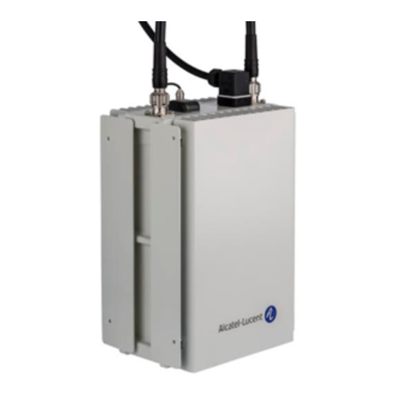
Physical description Product overview The Alcatel-Lucent 9764 Compact Metro Cell Outdoor is housed in an Alcatel-Lucent generic metallic case. The product is designed to be deployed close to the users, usually in streets on light poles or on walls of buildings, with a vertical profile that hides cable connectors and mounting kit for a smooth integration into the surrounding environment. - Page 24 Provides power to a remote Powered Dual SFP Device (PD) for Power over SFP/Power over Ethernet Ethernet (PoE)+ case. (PoE)+ Weights and dimensions The physical dimensions of the 9764 CMCO are: ..............................................Alcatel-Lucent – Proprietary Use pursuant to applicable agreements...
- Page 25 155 mm (6.1 in), including solar shield Volume 7.4 L Weight 7 Kg Alcatel-Lucent 9764 Compact Metro Cell Outdoor overview The 9764 CMCO is made up of three main units which are responsible for radio, digital processing and power supply functions. Unit Function...
- Page 26 Dual SFP backhaul module SFP/Power over Ethernet (PoE)+ backhaul module The backhaul and daisy chaining cables are routed through the cable glands below the backhaul module..............................................Alcatel-Lucent – Proprietary Use pursuant to applicable agreements...
- Page 27 In order to protect the power connector, a cover for the power connector must be installed. The figure below shows the power connector with cover. Figure 2-4 Power connector cover Power connector over ..............................................Alcatel-Lucent – Proprietary Use pursuant to applicable agreements...
- Page 28 (BH1). Therefore any supported Powered Device (PD) must be the main backhaul unit. Figure 2-5 Backhaul module variants Backhaul module variants SFP/PoE (RJ45) Dual SFP Detachable backhaul module backhaul module backhaul module ..............................................Alcatel-Lucent – Proprietary Use pursuant to applicable agreements...
- Page 29 A 9764 CMCO product label provides the following information: Model name Part number Serial number MAC address Power input range CE Approval marking Environmental marking (WEEE/RoHS) applicable to the device ..............................................Alcatel-Lucent – Proprietary 2-10 Use pursuant to applicable agreements...
-
Page 30: Supported Installation Options
..............................................Supported installation options Overview The following section describes the supported installation options for the Alcatel-Lucent 9764 Compact Metro Cell Outdoor product. These include: Standard installation options for all 9764 CMCO products. Daisy chain installation options where two 9764 CMCO modules are daisy chained together and share the same backhaul port. - Page 31 PoE+ backhaul module. In a daisy chained configuration, the PoE+ backhaul module can be used only for the “Head-CMCO”. Note: The following restriction applies: The PoE+ backhaul module does not support a GPON SFP..............................................Alcatel-Lucent – Proprietary 2-12 Use pursuant to applicable agreements...
- Page 32 When pair-mounting two 9764 CMCO modules, horizontal and vertical tilting can be used in order to avoid the overlap of radiation patterns. The following figure shows examples of two pair-mounted 9764 CMCOs with horizontal tilt..............................................Alcatel-Lucent – Proprietary 2-13 Use pursuant to applicable agreements...
- Page 33 Co-located configuration Two 9764 CMCOs can be mounted in a co-located configuration either in the same plane, or one above the other..............................................Alcatel-Lucent – Proprietary 2-14 Use pursuant to applicable agreements...
- Page 34 50 cm to 2m. Street furniture installation The Alcatel-Lucent 9764 Compact Metro Cell Outdoor can be installed as part of street furniture, for example, bus stops and advertising boards, to further improve the quality of service provided to users in high density areas such as city centers.
-
Page 35: Hardware And Ancillary Items
Hardware and ancillary items ..............................................Hardware and ancillary items Overview The following section lists the Alcatel-Lucent 9764 Compact Metro Cell Outdoor base hardware equipment, the installation kits and ancillary items that can be ordered from Alcatel-Lucent. 9764 CMCO base items The product packaging contains the following base items: ... - Page 36 (2m. 4.5m, 9m, 12m) markets) Grounding Item Description Ground cable Required for International markets Ground cable,Y/G 10mm² in 100m roll Ground cable Ground cable, 8 AWG Required for North America Regional markets ..............................................Alcatel-Lucent – Proprietary 2-17 Use pursuant to applicable agreements...
- Page 37 GPS antenna and cable loss <10dBi @ 1575MHz GPS antenna External GPS Antenna, 1575 Used if 9764 CMCO is configured for MHz*40 dBi external GPS antenna and cable loss >10dBi @ 1575MHz ..............................................Alcatel-Lucent – Proprietary 2-18 Use pursuant to applicable agreements...
- Page 38 When selecting Ethernet cables, the following requirements must be taken into account: Item Description Electrical Ethernet cable Optional Cathegory: CAT5e and CAT6 support 1 Gigabit/s Use with SFP GBE 10/100/1000BaseT Shielding types: S/UTP and SF/UTP: ..............................................Alcatel-Lucent – Proprietary 2-19 Use pursuant to applicable agreements...
- Page 39 Fiber Optic cable MM LC-LC 2MM 200m Fiber Optic cable MM LC-LC 2MM 250m Fiber Optic cable MM LC-LC 2MM 300m Solar shield Item Description Solar shield Solar Shield for Compact MCO Optional ..............................................Alcatel-Lucent – Proprietary Use pursuant to applicable agreements...
- Page 40 Overview Purpose This chapter provides pre-installation information (including required tools and materials and installation clearances) as well as outlining the possible daisy chain deployment scenarios and requirements for the Alcatel-Lucent 9764 Compact Metro Cell Outdoor product. Contents Pre-installation information Installation clearances...
-
Page 41: Pre-Installation
Packing List, immediately notify the carrier that delivered the unit and contact your Alcatel-Lucent representative. The product packaging contains the following items: The Alcatel-Lucent 9764 Compact Metro Cell Outdoor Installation materials In addition to the standard product deliverable ensure the appropriate mounting brackets, installation kits and ancillary items are available to support the product mounting options. - Page 42 Hammer PIB (self-amalgamating) tape and 3M Super 33+ vinyl tape Ear protectors and safety goggles/glasses Assorted cable ties (various lengths) Heavy duty tape Adjustable straps ..............................................Alcatel-Lucent – Proprietary Use pursuant to applicable agreements...
-
Page 43: Installation Clearances
To aid natural air convection. Front 460 mm (18.11 inch) Access to secure the solar shield cover. Rear 20 mm (0.79 inch) For the wall mounting space. To aid natural air convection..............................................Alcatel-Lucent – Proprietary Use pursuant to applicable agreements... -
Page 44: Pole Mount Installation Requirements
Pole mount installation requirements Purpose This topic outlines the basic requirements, installation kits and recommended anchor materials when mounting the Alcatel-Lucent 9764 Compact Metro Cell Outdoor directly onto a pole, onto tilt brackets or onto a pair mount bracket. Pole mount options The 9764 CMCO can be easily mounted onto a pole for the following installation options: ... - Page 45 Pre-installation Pole mount installation requirements ..............................................Figure 3-3 Pole mount banding and brackets Pole mount with tilt Pole mount no tilt ..............................................Alcatel-Lucent – Proprietary Use pursuant to applicable agreements...
-
Page 46: Wall Mount Installation Requirements
Wall mount installation requirements Purpose This topic outlines basic requirements, installation kits and recommended anchor materials when mounting the Alcatel-Lucent 9764 Compact Metro Cell Outdoor onto a solid concrete wall or flat surface or onto tilt brackets. Wall mount options... - Page 47 The following figures show examples of 9764 CMCO wall mount installation and wall mount installation with horizontal/vertical tilt. Figure 3-4 9764 CMCO wall mount examples Wall mount horizontal Wall mount no tilt Wall mount horizontal tilt only and vertical tilt ..............................................Alcatel-Lucent – Proprietary Use pursuant to applicable agreements...
-
Page 48: Installation
Purpose This chapter provides the instructions for: Cabling the MCO Compact backhaul module before installing the Alcatel-Lucent 9764 Compact Metro Cell Outdoor. Mounting the 9764 CMCO onto either a pole or wall with or without the optional tilt mechanism in various configurations (pair-mount and other co-located configurations). -
Page 49: Pre-Installation Cabling
This section provides instructions for routing and connecting the following cables to the MCO Compact backhaul module, depending on the network configuration, before the Alcatel-Lucent 9764 Compact Metro Cell Outdoor is mounted onto a surface: Fiber optic cable (for optical backhaul), or ... -
Page 50: Procedure 4-1: Ethernet Cabling - Fiber Optic
This topic describes the procedures to be followed when connecting the optical Ethernet cable to the Alcatel-Lucent 9764 Compact Metro Cell Outdoor. The 9764 CMCO may either be in a single configuration, or daisy chained to a second 9764 MCO. - Page 51 2. Momentarily touch the ESD clip onto a bare (unpainted) metal spot so that any built up static charge is dissipated. 3. Attach the ESD clip to the MCO ground lug screw (the ground lug screw can be unscrewed slightly for easier ESD clip attachment)..............................................Alcatel-Lucent – Proprietary Use pursuant to applicable agreements...
- Page 52 Align the backhaul optical SFP cable from the backhaul system. transceiver module with the SFP port labelled “BH 1” and insert the module into the socket until you feel the connector latch into place..............................................Alcatel-Lucent – Proprietary Use pursuant to applicable agreements...
- Page 53 Ethernet cable is correctly routed to this 9764 MCO........................................Unscrew and remove the rounded compression nut from the cable gland located on the bottom of the bottom of the backhaul module..............................................Alcatel-Lucent – Proprietary Use pursuant to applicable agreements...
- Page 54 Remove dust plugs from the optical cable connectors and the SFP transceiver module and immediately insert the cable connectors into the SFP transceiver in the port labelled “BH 1”. BH2 port BH1 port ..............................................Alcatel-Lucent – Proprietary Use pursuant to applicable agreements...
- Page 55 Screw the rounded compression nut back onto the main body of the gland. Use an adjustable or open-end wrench to tighten the compression nut. Important! Alcatel-Lucent recommends that the compression nut is torqued to 2.5 N m (1.8 lb.ft) in order to create a watertight seal and avoid a potential loose connection.
- Page 56 Secure cables with cable clips. Use additional clips wherever necessary for neatness. All cables should be run parallel with no twisting or tangled cables. Avoid excessive tension on the cables..................................................................................Alcatel-Lucent – Proprietary 4-10 Use pursuant to applicable agreements...
-
Page 57: Procedure 4-2: Ethernet Cabling - Electrical
This topic describes the procedures to be followed when connecting an electrical Ethernet cable to the Alcatel-Lucent 9764 Compact Metro Cell Outdoor. The 9764 CMCO may either be in a single configuration, or daisy chained to a second 9764 MCO. - Page 58 2. Momentarily touch the ESD clip onto a bare (unpainted) metal spot so that any built up static charge is dissipated. 3. Attach the ESD clip to the MCO ground lug screw (the ground lug screw can be unscrewed slightly for easier ESD clip attachment)..............................................Alcatel-Lucent – Proprietary 4-12 Use pursuant to applicable agreements...
- Page 59 Align the backhaul electrical SFP cable from the backhaul system. transceiver module with the SFP port labelled “BH 1” and insert the module into the socket until you feel the connector latch into place..............................................Alcatel-Lucent – Proprietary 4-13 Use pursuant to applicable agreements...
- Page 60 9764 CMCO or the optional internal surge arrestor module (if installed)........................................Obtain, from the packaging, the Alcatel-Lucent electrical Ethernet cable. The RJ45 connector without connector cover should be used at the 9764 CMCO side. Note: If an external surge arrestor is installed then use a short cable from the surge arrestor to the 9764 CMCO.
- Page 61 Ethernet cable, as shown: ........................................Pull the cable through the gland assembly parts until a connection is made between the exposed cable screen braid and the gland contact springs..............................................Alcatel-Lucent – Proprietary 4-15 Use pursuant to applicable agreements...
- Page 62 Important! It is recommended that the compression nut is torqued to 2.5 N.m (22.1 lb.in) in order to create a watertight seal and avoid a potential loose connection..............................................Alcatel-Lucent – Proprietary 4-16 Use pursuant to applicable agreements...
- Page 63 Tighten the four retention screws in the sequence shown. Recommended torque, 2.0 N.m (17.7 lb.in)........................................Finally, secure the Ethernet cable to the wall or pole..............................................Alcatel-Lucent – Proprietary 4-17 Use pursuant to applicable agreements...
- Page 64 Plug the Ethernet cable RJ45 connector into the upper connector on the arrestor. Screw the weatherized strain relief connector back onto the arrestor and tighten........................................Finally, secure the Ethernet cable to the wall/pole..............................................Alcatel-Lucent – Proprietary 4-18 Use pursuant to applicable agreements...
- Page 65 Secure cables with tie wraps. Use additional tie wraps wherever necessary for neatness. All cables should be run parallel with no twisting or tangled cables. Avoid excessive tension on the cable..................................................................................Alcatel-Lucent – Proprietary 4-19 Use pursuant to applicable agreements...
-
Page 66: Installation
This section provides the installation instructions for: mounting the Alcatel-Lucent 9764 Compact Metro Cell Outdoor onto either a pole or wall with or without the optional tilt mechanism, ... -
Page 67: Procedure 4-3: Pole Mount The 9764 Cmco
For a list of standard tools that may be required to support the installation, see “Tools required for installation” (p. 3-3). Before you begin Record the 9764 CMCO 18 digit serial number before mounting onto a pole..............................................Alcatel-Lucent – Proprietary 4-21 Use pursuant to applicable agreements... - Page 68 At the marked installation point on the pole place the bands around the pole at the determined height. Carry out any required adjustment of the mounting bracket around the pole so that it is pointing in the desired direction..............................................Alcatel-Lucent – Proprietary 4-22 Use pursuant to applicable agreements...
- Page 69 Proceed with the next step. used Notes: Although optional, Alcatel-Lucent strongly recommends for outdoor deployments, that when the backhaul connection is configured for electrical Ethernet (GBE 10/100/1000BaseT) a surge arrestor is installed, as the electrical SFP does not provide surge protection.
- Page 70 Attach the 9764 CMCO to the bracket by sliding the 9764 CMCO forwards and downwards onto the bracket mounting lugs........................................Secure the 9764 CMCO onto the mounting frame by tightening the lever retaining screw..............................................Alcatel-Lucent – Proprietary 4-24 Use pursuant to applicable agreements...
- Page 71 To prevent a fall when working at heights (ladder, scaffold, manlift, roof etc.) follow safe work practices and wear appropriate fall protection equipment. Although optional, Alcatel-Lucent strongly recommends for outdoor deployments, that when the backhaul connection is configured for electrical Ethernet (GBE 10/100/1000BaseT) a surge arrestor is installed, as the electrical SFP does not provide surge protection.
- Page 72 Screw the arrestor locking nut back onto the arrestor and tighten so that the arrestor is securely attached to the bracket. External surge arrestor ....................................Standard pole mount example The following figure depicts a 9764 CMCO standard pole mount using pole bands..............................................Alcatel-Lucent – Proprietary 4-26 Use pursuant to applicable agreements...
- Page 73 50 cm to 2m. How to continue After mounting the 9764 CMCO onto a pole the cables need to be connected. Continue with the Chapter 5, “Cabling” chapter..............................................Alcatel-Lucent – Proprietary 4-27 Use pursuant to applicable agreements...
-
Page 74: Procedure 4-5: Wall Mount The 9764 Cmco
..............................................Procedure 4-4: Wall mount the 9764 CMCO Purpose This topic describes the procedures to be followed when installing the Alcatel-Lucent 9764 Compact Metro Cell Outdoor onto a wall or solid flat surface Prerequisites A site survey has been conducted and a location for the device has been selected that is both central to the public space and elevated in order to maximize coverage. - Page 75 At the selected installation location, mark the points on the wall for the mounting bracket anchor holes. See drill hole pattern below to use as a guide: 75 mm 3.0 inches 75 mm 3.0 inches 190 mm 190 mm 7.5 inches 7.5 inches ..............................................Alcatel-Lucent – Proprietary 4-29 Use pursuant to applicable agreements...
- Page 76 ........................................To attach the 9764 CMCO to the mounting bracket open the mounting frame lever by pulling the lever outwards..............................................Alcatel-Lucent – Proprietary 4-30 Use pursuant to applicable agreements...
- Page 77 Secure the 9764 9764 CMCO onto the mounting frame by tightening the lever retaining screw........................................Finally, check the 9764 CMCO is correctly locked into position and there is no movement of the module on the mounting frame..................................................................................Alcatel-Lucent – Proprietary 4-31 Use pursuant to applicable agreements...
- Page 78 To prevent a fall when working at heights (ladder, scaffold, manlift, roof etc.) follow safe work practices and wear appropriate fall protection equipment. Although optional, Alcatel-Lucent strongly recommends for outdoor deployments, that when the backhaul connection is configured for electrical Ethernet (GBE 10/100/1000BaseT) a surge arrestor is installed, as the electrical SFP does not provide surge protection.
- Page 79 The following figure depicts a standard 9764 CMCO wall mount installation. How to continue After mounting the 9764 CMCO onto a wall or flat surface the cables need to be connected. Continue with the Chapter 5, “Cabling” chapter ..............................................Alcatel-Lucent – Proprietary 4-33 Use pursuant to applicable agreements...
-
Page 80: Cabling
Cabling Overview Purpose This chapter provides instructions for routing and connecting the following cables to the Alcatel-Lucent 9764 Compact Metro Cell Outdoor: Ground cable External RF antenna cable External GPS antenna cable Power cable Contents Procedure 5-1: Connect ground cable... -
Page 81: Procedure 5-1: Connect Ground Cable
..............................................Procedure 5-1: Connect ground cable Purpose Follow this procedure to connect the ground cable to the Alcatel-Lucent 9764 Compact Metro Cell Outdoor. Before you begin Ensure the following: All site preparation activities for cabling have been completed. All installation procedures for the 9764 CMCO have been completed. - Page 82 Cabling ..............................................Figure 5-1 Position of grounding point Double lug ground point ........................................Finally, secure the grounding cable to the wall or pole..................................................................................Alcatel-Lucent – Proprietary Use pursuant to applicable agreements...
-
Page 83: Procedure 5-2: Connect Rf Antennas
Procedure 5-2: Connect RF antennas Purpose Two RF antenna connectors are located externally on the top of the Alcatel-Lucent 9764 Compact Metro Cell Outdoor, giving the service provider the option of either connecting an attached RF antenna or connecting to two externally cabled RF antennas. - Page 84 9764 CMCO by pressing the two levers (1 in the figure below) and sliding the solar shield (2 in the figure) upwards. No tools are required to do this..............................................Alcatel-Lucent – Proprietary Use pursuant to applicable agreements...
- Page 85 Connect each antenna cable by pushing the antenna cable connector onto the N-type connector on the top of 9764 CMCO and firmly tighten the connectors by hand. RF antenna connector RF antenna connector Lever Lever Solar shield RF antenna ................................................................................... Alcatel-Lucent – Proprietary Use pursuant to applicable agreements...
- Page 86 9764 Compact MCO (top view) ........................................Connect each RF adapter cable by pushing the adapter cable connector onto the 9764 CMCO N-type connector until it clicks into place..................................................................................Alcatel-Lucent – Proprietary Use pursuant to applicable agreements...
-
Page 87: Procedure 5-3: Connect Gps Antenna
Procedure 5-3: Connect GPS antenna Purpose Use this procedure to connect an external (remote) GPS antenna cable to the Alcatel-Lucent 9764 Compact Metro Cell Outdoor. Integrated GPS antenna The 9764 CMCO is supplied with an integrated GPS antenna attached to the top of the MCO, and connected to the QMA connector on the top of the MCO. - Page 88 Falls can occur when working at heights resulting in serious personal injury or death. To prevent a fall when working at heights (ladder, scaffold, manlift, roof etc.) follow safe work practices and wear appropriate fall protection equipment..............................................Alcatel-Lucent – Proprietary Use pursuant to applicable agreements...
- Page 89 Refer to the GPS antenna mounting instructions included with the GPS antenna kit for the steps to mount the antenna........................................Locate the GPS antenna connector on the top of the 9764 CMCO..............................................Alcatel-Lucent – Proprietary 5-10 Use pursuant to applicable agreements...
- Page 90 CMCO QMA-type GPS antenna connector until it clicks into place. Cable connector MCO QMA connector ........................................Apply weatherizing tape at the point indicated by the red arrows shown in the following figure: ..............................................Alcatel-Lucent – Proprietary 5-11 Use pursuant to applicable agreements...
- Page 91 Cabling ..............................................First, apply Linerless rubber splicing tape, then apply vinyl electrical tape over the Linerless rubber splicing tape..................................................................................Alcatel-Lucent – Proprietary 5-12 Use pursuant to applicable agreements...
-
Page 92: Procedure 5-4: Connect Power Cable
(connector attached) 9764 Compact MCO (top view) Power cable The 9764 CMCO is equipped with a DIN Valve Connector. The Alcatel-Lucent supplied power cable and connector should be used with this equipment. Before you begin Depending on whether your 9764 CMCO requires AC power, select the appropriate procedure from the following table: If... - Page 93 Ensure that the power that feeds the AC power cable to the 9764 CMCO is OFF, and block access so that no one can restore power to that cable during this procedure........................................Cut the power cable to the required length..............................................Alcatel-Lucent – Proprietary 5-14 Use pursuant to applicable agreements...
- Page 94 Strip the cable according to the dimensions in the figure below. Assuming an H12 ground position, the longest wire is the ground wire. Blue Green/yellow Brown 8 mm (0.32 in) 40 mm (1.6 in) ..............................................Alcatel-Lucent – Proprietary 5-15 Use pursuant to applicable agreements...
- Page 95 Screw the wires into the terminal blocks to a torque of 0.4 Nm. Attention: Ensure that you connect the Live, Neutral, and Ground wires to the correct pins as shown in the following figure: ..............................................Alcatel-Lucent – Proprietary 5-16 Use pursuant to applicable agreements...
- Page 96 Fix the AC power connector in position by tightening the screw on the AC power connector. Using a screwdriver with a Phillips head, torque to 0.4 Nm (0.295 lb ft)..................................................................................Alcatel-Lucent – Proprietary 5-17 Use pursuant to applicable agreements...
- Page 97 Fix the AC power connector in position by tightening the screw on the AC power connector. Using a screwdriver with a Phillips head, torque to 0.4 Nm (0.295 lb ft)..............................................Alcatel-Lucent – Proprietary 5-18 Use pursuant to applicable agreements...
- Page 98 Power connection point on 9764 CMCO ........................................Lower the power connector cover over the power connector, align the captive TORX M3x5 attachment screw on the power connector cover with the screw hole in the 9764 CMCO, and fix the power connector cover in position by inserting the screw into the screw hole and tightening.
-
Page 99: Post-Installation
6 Post-installation OVERVIEW This chapter provides post-installation information and activities that should be carried out after the Alcatel-Lucent 9764 Compact Metro Cell Outdoor has been Purpose installed. Contents Procedure 6-1: Final installation activities and checks ..............................................Alcatel-Lucent 9764 CMCO Alcatel-Lucent – Proprietary... -
Page 100: Overview
Procedure 6-1: Final installation activities and checks ..............................................Procedure 6-1: Final installation activities and checks Overview This topic describes the final Alcatel-Lucent 9764 Compact Metro Cell Outdoor installation activities and checks to be carried out. Use pursuant to applicable agreements... - Page 101 Final installation checks Before leaving the installation site, check the following: ........................................Check the overall installation. Verify that mounted equipment is secure and that no unintentional mechanical alteration has occurred to either the equipment itself or the installation infrastructure........................................Ensure all the exterior connections are secure.
- Page 102 Appendix A: LED state description Overview Purpose This chapter describes the LED status and descriptions for 9764 CMCO. Contents LED status for 9764 CMCO ..............................................Alcatel-Lucent 9764 CMCO Alcatel-Lucent – Proprietary Use pursuant to applicable agreements...
-
Page 103: Led State Description
LED state description LED status for 9764 CMCO ..............................................LED status for 9764 CMCO Overview This topic describes the LED status on the 9764 CMCO device. Location of LED The following figure shows the location of the LED on the back of the 9764 CMCO: Figure C-1 Location of LED Hardware LED interpretation table The following table describes the possible states for the single bi-color LED:... - Page 104 LED state description LED status for 9764 CMCO ..............................................State Description 9764 MCO LTE is operational 9764 MCO LTE has been in stable operation for 15 minutes Use pursuant to applicable agreements...
-
Page 105: Overview
Overview Purpose This section presents the product conformance statements that apply to the Alcatel-Lucent 9764 Compact Metro Cell Outdoor Access Point equipment. The statements that are required are determined primarily by national or multinational regulations. However, in some regions, contract terms determine which statements are required. - Page 106 Directive 1999/5/EC. The technical documentation as required by the Conformity Assessment procedure is kept at the Alcatel-Lucent location which is responsible for this product. For more information please contact your local Alcatel-Lucent Customer Service Organization. Contents...
-
Page 107: European Union
CE marking Product conformance statements European Union ..............................................CE marking CE marking This product has been CE-marked in accordance with the following European Directives: 1999/05/EC Radio and Telecommunication Terminal Equipment (R&TTE) Use pursuant to applicable agreements... -
Page 108: Emc And Radio Spectrum Compliance
EN 301 908-3 V5.2.1 IMT cellular networks; Harmonized EN covering the essential requirements of article 3.2 of the R Directive; Part 3: CDMA Direct Spread (UTRA FDD) Base Stations (BS) ..............................................Alcatel-Lucent – Proprietary Use pursuant to applicable agreements... -
Page 109: Product Safety And Rf Exposure
Part 1: General Requirements A11 (2009) + A12 (2011) EN 60950-22 (Ed 1 of 2006) + A11 (2008) Information Technology Equipment – Safety – Part 22: Equipment to be installed outdoors ..............................................Alcatel-Lucent – Proprietary Use pursuant to applicable agreements... - Page 110 Note: These standards are aligned with the Guidelines of 1998 from the International Commission for Non-Ionizing Radiation Protection (ICNIRP). The recommendations provided below may also be extended to other ICNIRP based regulations..............................................Alcatel-Lucent – Proprietary Use pursuant to applicable agreements...
-
Page 111: Eco-Environmental Statements
Moreover, in compliance with legal requirements and contractual agreements, where applicable, Alcatel-Lucent will offer to provide for the collection and treatment of Alcatel-Lucent products bearing the logo at the end of their useful life, or products displaced by Alcatel-Lucent equipment offers. - Page 112 Takeback Support at (mailto:takeback@alcatel-lucent.com). For technical information on product treatment, consult the Alcatel-Lucent Recycling Information (http://www.alcatel-lucent.com/product_recycling) web page. Material content compliance European Union The European Union (EU) Restriction of the Use of Certain Hazardous Substances in Electrical and Electronic Equipment (RoHS) Directive [2002/95/EC and its recast...
Need help?
Do you have a question about the 9764 Series and is the answer not in the manual?
Questions and answers