LG A005KEEN261 Manual

LG A005KEEN261 Manual

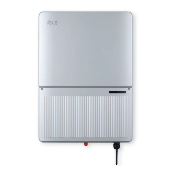
Energy storage system

Advertisement

19/02/2019
MANUAL
Energy Storage
System
Please read this manual carefully before installing
your equipment and retain it for future reference.
MODEL
A005KEEN261
D007KEEN261
www.lg.com/b2b
Copyright © 2019 LG Electronics Inc. All Rights Reserved.

Advertisement

Table of Contents
loading

Summary of Contents for LG A005KEEN261

  • Page 1 19/02/2019 MANUAL Energy Storage System Please read this manual carefully before installing your equipment and retain it for future reference. MODEL A005KEEN261 D007KEEN261 www.lg.com/b2b Copyright © 2019 LG Electronics Inc. All Rights Reserved.
  • Page 2: Important Safety Instructions

    This manual contains important instructions for the installation and maintenance of the LG Electronics ESS inverter. LG Electronics ESS inverters are designed and tested to meet all applicable North American and International safety standards. However, like all electrical and electronic equipment, safety precautions must be observed and followed during installation and operation of the LG Electronics ESS inverters to reduce the risk of personal injury and to ensure a safe installation.
  • Page 3: Safety Instructions

    LG Electronics Authorized Service Center. y Read all of these instructions, cautions, and warnings for the LG Electronics ESS inverter and associated ESS equipment (PV panel, RSD, Battery pack, ATS, Energy meter, etc.) documentation.
  • Page 4: Table Of Contents

    Table of Contents Table of Contents Getting Started IMPORTANT SAFETY INSTRUCTIONS . . . . . . . . . . . . . . . . . . . . . . . . . . . . . . . . . . . . . . . . . . . . 2 General safety instructions .
  • Page 5 Installing 'LG EnerVu2 Professionals' App ........
  • Page 6: Introduction

    The string concept means that PV modules are always connected in series (in a string) and/or that strings with the same voltage are connected in parallel to the LG Electronics ESS inverter with the aim of significantly reducing the photovoltaic system’ s cabling requirements.
  • Page 7 The maximum number of PV strings is three. For the AC- coupled system, there is the option to have no solar modules connected to the LG Electronics ESS inverter at all, and the PV power option will be deactivated.
  • Page 8 A powerful tool for monitoring, configuration or diagnostics, the App is connected to the inverter via Bluetooth. LG Electronics Cloud The inverter communicates with the LG Electronics cloud via a WiFi gateway installed within the inverter. Also, the WiFi gateway can push data directly to the customer’ s cloud or third-party cloud.
  • Page 9: Equipment Overview

    Getting Started Equipment overview < Exterior view of inverter main components > Inverter Power Box - This is the inverter section of the assembly. This section is sealed at the factory and there are no user-serviceable parts inside. All wiring to install the inverter is done in the wiring box.
  • Page 10: Inverter Type And Safety Labels

    Please note that capital letters in Serial Number are used as placeholders to indicate the variable information for the LG Electronics ESS. The main caution labels in English and French are on the right side of the inverter.
  • Page 11 Getting Started 16.73” (425 mm) < Dimensions of ESS inverters >...
  • Page 12 Getting Started < Wiring box of inverters > PV and Battery terminals RS485 communication ports BAT Fuse Holders CAN and RS485 communication ports Grounding Ethernet and RS485 communication ports AC terminal Required torques for wiring box terminals Terminals Wire size permitted* Torque 3 (Grounding) 10 - 8 AWG...
  • Page 13: Installation

    Installation Installation General safety WARNING Please read all of these instructions, cautions, and warnings for the LG Electronics ESS inverter and associated PV array documentation. WARNING Installation and commissioning must be performed by a licensed electrician in accordance with local, state, and National Electrical Code ANSI/NFPA 70 requirements.
  • Page 14: Visual Inspection

    Manual d. Wi-Fi antenna Visually inspect the LG Electronics ESS inverter for any physical damage such as a bent heatsink fin and dented chassis. If the inverter appears to be damaged or if the inverter needs to be returned, please contact your local LG Electronics representative.
  • Page 15: Installation Location

    Installation Installation location y Install the inverter on a non-flammable support base. y The inverter must be mounted vertically on a flat surface. y A minimum distance of 6” (15.2 cm) of unobstructed clearance between the inverter and other equipment and 4” (10 cm) between the inverter and a corner is required to promote free convection.
  • Page 16 Installation Inverter should be at least >= 20” (50.8 cm) 20” (50.8 cm) from any ceiling surface >= 4” (10 cm) >= 6” (15.2 cm) >= 6” (15.2 cm) Inverter should be mounted >= 39” (100 cm) at least 39” (100 cm) from the floor or ground surface.
  • Page 17 Installation M6 * 2 < Installing the plate and inverter on a wood stud wall > A Using the mounting plate as a template, mark four screw holes onto the wall. For 16" (40.6 cm) on center stud mounting, use the four holes that are indicated for this purpose in the figure. Make sure at least two of the holes are in the center of a stud before marking the drill location.
  • Page 18: Electrical Connections

    Installation Electrical connections General safety DANGER PV solar arrays produce hazardous voltages and currents when exposed to light, which can create an electrical shock hazard. Use dark opaque sheets to cover the PV solar array before wiring or connecting cable terminations. WARNING Read all of these instructions, cautions, and warnings for the inverter and associated PV array.
  • Page 19: Utility Ac Voltage

    208 V AC or 240 V AC 60 Hz public utility grids. CAUTION The LG Electronics ESS Inverters should never be connected to a 120 V AC utility service. NEC 705.12 requires that the inverter be connected to a dedicated circuit with no other outlets or devices connected to the same circuit.
  • Page 20 Installation < 208 V / 120 V WYE AC Grid > < 240 V Inverter AC Grid > < 240 V / 120 V Stinger AC Grid > Public Grid Configuration NOT Allowed: < 480 V DELTA AC Grid > <...
  • Page 21: Ac Circuit Breaker Requirements

    Installation AC circuit breaker requirements A dedicated circuit breaker in the building panelboard is required for each LG Electronics ESS inverter that is installed. There should be a circuit breaker or fuse to protect each AC line, L1 and L2. The circuit breaker should be able to handle the rated maximum output voltage and current of the inverter.
  • Page 22: Pv String Considerations

    Installation PV string considerations There are a large number of PV module string combinations that will offer optimal performance from the DC-coupled type inverters due to its wide MPP range (50 V – 450 V). WARNING Use the PV module manufacturer specified V/Temp coefficient or the temperature multiplication factors given in the table in NEC 690.7 to ensure PV string voltage is less than 450 V DC.
  • Page 23: Inverter Connections

    Installation Inverter connections General information DANGER PV solar arrays produce hazardous voltages and currents when exposed to light, which can create an electrical shock hazard. Use dark opaque sheets to cover the PV solar array before wiring or connecting cable terminations. WARNING Installation and commissioning must be performed by a licensed electrician in accordance with local, state, and National Electrical Code ANSI/NFPA 70 requirements.
  • Page 24: Opening The Wiring Box Cover

    Installation Opening the wiring box cover WARNING Ensure no live voltages are present on PV input and AC output circuits, and verify that the DC disconnect, AC disconnect, and dedicated AC branch circuit breaker are in the [OFF] position before inverter installation. (M4-0.7 X 16mm) <...
  • Page 25: Wiring Box Conduit Plugs

    Installation Wiring box conduit plugs Conduit plugs are provided for 3/4“ and 1/2“ conduit fittings. If conduit fitting used is between 3/4“ and 1/2“ , an appropriate conduit reducer should be used. 3/4” 3/4” 1/2“ 3/4” 3/4” 3/4” < Locations of wiring box conduit plugs > CAUTION Do not enlarge the wiring compartment conduit openings, as the wiring box enclosure will be damaged, which will void the inverter warranty.
  • Page 26 Installation 0.7” (1.78 cm) 6” (15.24 cm) < Conduit installation and wiring routing > Conduit fittings need to be watertight with either NEMA4, 4X, 6, or 6X rated, and an insulated type is preferred. Once conduit and fittings are installed, route wiring through conduit and fitting, allowing a 6”...
  • Page 27: Pv Array String Input Connections (Only For Dc-Coupled Type)

    Installation PV array string input connections (Only for DC-coupled type) DANGER To ensure maximum protection against hazardous contact voltages while assembling photovoltaic installations, both the positive and the negative leads must be strictly isolated electrically from the protective ground potential (PE). WARNING y Risk of electric shock and fire.
  • Page 28 Installation < Wiring box of inverters > PV1 Positive Terminals PV1 Negative Terminals PV2 Positive Terminals PV2 Negative Terminals PV3 Positive Terminals PV3 Negative Terminals A Verify that the exposed wires are at least 6” (15.24 cm) in length to provide adequate strain relief and wire end strip length required.
  • Page 29: Pv Switch Lock Out And Tag Out Procedure

    Installation PV switch LOCK out and TAG out procedure A Remove power to the System by turning each OFF POSITION operation handle of the main circuit breaker to the [OFF] Position. Then lockout each circuit breaker as shown below. ON POSITION B Attach a padlock.
  • Page 30: Battery Wire Connections

    Installation Battery wire connections < Wiring box of inverters > Battery Positive Terminals Grounding Battery Negative Terminals A Verify that the exposed wires are at least 6" (15.24 cm) in length to provide adequate strain relief and wire end strip length required. B Connect the positive lead to Battery Positive Terminals ( C Connect the negative lead to Battery Negative Terminals ( D Verify that connections to the DC wiring board assembly are properly wired.
  • Page 31: Battery Communication Cable Connection

    Installation Battery communication cable connection B- A+EN GND < Wiring box of inverters > A Strip four wires of the battery pack communication cable and insert stripped wire-ends to the corresponding wire hole on the plug. B Match the names in the figure with the connectors on battery pack. a b c d...
  • Page 32: Battery Pack Connections

    Installation Battery pack connections Connection Power / Communication cables, according to the labels marked. INFO y Commissioning should be within 180 days of manufacture date. Verify this via the unit serial number. y Battery cables are recommended to be 12 – 8 AWG. A Connect the power cables to the corresponding terminals.
  • Page 33 Installation C Connecting the battery pack to the inverter. circuit breaker For the inverter to connect the power cable and communication cable to the inverter. Then, push the disconnect switch up so that it is in the ON position. INFO The battery must be turned off during shipping and storage to reduce self-discharge.
  • Page 34: Energy Meter Connections

    Installation Energy meter connections The energy meter connection is required to get information about energy flow. Before connecting the energy meter to this product, install the energy meter. Refer to the installation manual of the energy meter for more information about energy meter installation. INFO AC wire cables are recommended to be 22 –...
  • Page 35 Installation Energy meter connection case1 Power Distribution Box Utility Grid EN GND Household Energy meter connection case2 Power Distribution Box Utility Grid EN GND Household * Additional CT is required. (CT’ s only offered in one pair.) Please contact the service center before installing.
  • Page 36 Installation Power Status LED LED color Function Indication Troubleshooting Green Flashing ON/OFF Working normally (for 1 second) ON for > 3 seconds Internal error Contact support Check that the Flashing ON/OFF Yellow No communication communication wires are (for 1 second) connected correctly.
  • Page 37: Energy Meter Connections (Inverter Side)

    Installation Energy meter connections (Inverter Side) A Strip two wires of the energy meter cable and insert stripped wire-ends to the corresponding wire hole on the plug. B Match the names in the figure with the connectors on the energy meter. B- A+EN GND...
  • Page 38: Inverter Ac Output Wire Connections

    Inverter AC output wire connections WARNING y Read all of the instructions, cautions, and warnings for the LG Electronics ESS Inverter, and associated PV array documentation. y Installation and commissioning must be performed by a licensed electrician in accordance with local, state, and National Electrical Code ANSI/NFPA 70 requirements.
  • Page 39 Installation < Wiring box AC assembly – terminal labeling > L1 Terminal L2 Terminal N Terminal Ground WARNING An AC disconnect may be required by your local AHJ. Please check local regulations to determine if an AC disconnect is required for your installation. NOTICE Stranded copper wire should be checked so that all strands go into the terminal opening.
  • Page 40 Installation E Terminate inverter’ s AC output wires inside the AC disconnect or wiring box. - Connect the Neutral wire to the terminal ( - Connect L1 wire to the terminal ( - Connect L2 wire to the terminal ( - Use a 1/8”...
  • Page 41: Ats Wire Connections

    Installation ATS wire connections INFO Before the ATS connection need to install a secondary AC panel for backed-up loads (not supplied by LGE). Rewire the backed-up loads through this panel. A Open the cover y Unscrew the 4 screws on cover with a Torx20 screwdriver and remove the cover.
  • Page 42 Installation F Connect the wire (GND) to the Grounding terminal. y 2x Grounding Electrode Conductor is provided, it is a slot head screw type connector. The terminals accept solid or stranded copper 10-4 AWG wire, recommended screw torque is 26 in-lbs (2.9 Nm). Grounding NOTICE y Verify the connection firmly again.
  • Page 43: Inverter Communication Connections

    Installation Inverter communication connections WARNING Read all of these instructions, cautions, and warnings for the LG Electronics ESS inverter and associated ESS equipment (PV panel, RSD, Battery pack, ATS, Energy meter, etc.) documentation. Interface connection communication The LG Electronics ESS inverters offer an EIA RS485 communication interface that can address up to 31 daisy chained inverters.
  • Page 44 Installation < Ethernet and 485 communication ports > < RS485 communication ports (Energy meter and Battery) >...
  • Page 45: Wi-Fi Antenna Connection

    Installation Wi-Fi antenna connection A Take out the antenna. Make sure the sealant is installed well. B Take the cover off with tools. C Insert the antenna into the same hole and tighten with nut inside. D Connect the antenna with module.
  • Page 46: Operation

    NOTICE y Depending on the device, ‘LG EnerVu2 Professionals’ App may not work. y LG EnerVu2 Professionals App will be available in the version of the software as follows; - Android O/S : Lollipop (5.0) or higher - iOS O/S : iPhone 6 (9.0) or higher About the main screen The main screen displays system and cloud connection in the connections menu area.
  • Page 47: Connect Via Bluetooth

    Check the last 4 digits of the serial number and date code on the right side of the ESS unit. y The system owner must create a LG ESS account before accessing the system. Visit EnerVu2 page at http://enervu.lg-solar.com and sign up to create an account.
  • Page 48 Operation D Input the date code and select [OK] to connect to the system. The date code is a 4-digit number and is printed on the right side of the PCS. Date E When the connection is successful, the event screen appears as shown in the figure.
  • Page 49: Network Configuration

    Operation Network Configuration y This unit supports wired connection via Ethernet and wireless connection via WLAN for Enervu cloud connection. y Wireless connection and wired connection can be selected at the same time. The wired connection is connected first. y This unit does not support a static IP setting. y If you are using a wired connection, you can use the wired Ethernet connection to your home network without any setup.
  • Page 50: Ess System Settings

    - Grid Profile You can make detailed settings related to Rule21. CAUTION The grid profile must be set correctly. LG Electronics does not accept liability for a missing or incorrect grid profile. If you are not sure which grid profile data set is valid...
  • Page 51: Registering The Pcs (Mobile App)

    Operation Registering the PCS (Mobile App) A Tap [New System] button on the event screen. B Fill in the System & Home owner information. If you click the ‘Save’ button, an invitation e-mail or completion notice of registration will be sent to the homeowner's email typed in Owner Info, and the system will be created.
  • Page 52: Commissioning The Pv System

    Operation Commissioning the PV system WARNING Read all of these instructions, cautions, and warnings for the LG Electronics ESS inverter and associated PV array documentation. WARNING Installation and commissioning must be performed by a licensed electrician in accordance with local, state, and National Electrical Code ANSI/NFPA 70 requirements.
  • Page 53 Operation The LEDs indicate the operational status of the inverter LED Signals Message Message Explanation Example Category Color Status Behavior OPER LED Normal operation OPER Green <ON> constantly on The inverter feeds into the grid. Sync. OPER Green <BLINK> Four LEDs form a The inverter is synchronizing LED signals: or <ON>...
  • Page 54 Operation LED Signals Message Message Explanation Example Category Color Status Behavior INFO LED Firmware upgrade INFO Yellow <BLINK> 1s on, 1s off Firmware upgrading is ongoing Reset button is INFO Green <BLINK> Varied behavior When reset button is pressed LED signals: pressed for different time duration, the INFO LED is blinking with Green,...
  • Page 55: Button

    Operation Button Arc reset There is a button located inside the wiring box. For this button, there are the following functions. Button Application Trigger condition Arc reset Clear arc fault. Press the button for 3-5 seconds. If there is no arc fault, run arc Arc self-test Press the button for 3-5 seconds.
  • Page 56: Inverter Turn-On Procedure

    Operation Dark start Button Application Trigger condition During grid outage, when the whole system shutdowns for some reason, and can’t recover Press the button for more Dark start by itself. Press this button to wake up battery than 5 seconds. or the whole system.
  • Page 57: Appendix

    Appendix Maintenance Production information NOTICE All production information is provided for orientation purposes only. The measuring devices and meters provided by the electricity supply company are the authoritative source of information for invoicing. Repair DANGER Danger of death from hazardous voltage. Hazardous voltage is applied to the inverter during operation.
  • Page 58: Inspecting Regularly

    Disposal of the product must be carried out by qualified personnel only. Contact the authorized dealer where you purchased the LG Electronics ESS. Contact If you have technical problems or questions, contact the installation company or LGE.
  • Page 59: Troubleshooting

    Appendix Troubleshooting Event messages and troubleshooting can be easily found in the mobile app. A Tap [Support] button on the main screen. The event screen appears as shown in the figure. B Tap [ESS Event Guide] button on the support screen. The ESS event guide screen appears as shown in the figure.
  • Page 60 Appendix C There is more information on troubleshooting by selecting the TS number on the Solutions tab.
  • Page 61: Lge Open Source Software Notice

    This offer is valid for a period of three years after our last shipment of this product. This offer is valid to anyone in receipt of this information. Please be informed that this LG Electronics, Inc. product may contain open source software listed in the tables below.
  • Page 62: Specifications

    Appendix Specifications PV input LG AC 5kW LG DC 7.6kW Model Name A005KEEN261 D007KEEN261 Absolute Maximum Input Voltage 450 V DC Start-up Voltage 120 V DC Operational DC Voltage Range 50 – 450 V DC Full Power MPPT Range 270 – 450 V DC...
  • Page 63 Appendix AC Output (On-Grid Mode) LG AC 5kW LG DC 7.6kW 5000 W 8000 W Maximum Output Power a) 240 V AC +10%/-12%, (L-L) Grid Voltage Range b) 208 V AC +10%/-12%, (L-L) Maximum AC Current 24 A AC 32 A AC Frequency Range 59.3 –...
  • Page 64 Appendix General PV to AC LG AC 5kW LG DC 7.6kW Isolation Level Transformer-less Type of Converter DC/AC CEC Efficiency 97.50% Operating Temperature -22 °F – 149 °F/ -30 °C – 65 °C De-rating Start Temp. Higher than 113 °F (45 °C) Humidity 0 –...
  • Page 65 Appendix Accessory LG AC 5kW LG DC 7.6kW Rapid Shutdown Box Offered by LG Electronics Energy Meter Offered by LG Electronics Auto-Transfer Switch Offered by LG Electronics Standards Safety Mark General Safety UL1741, CSA 22.2 No. 107-01 Software Safety UL1998 Grid IEEE1547, IEEE1547.1...
  • Page 66: Fcc Compliance Information

    Appendix FCC compliance information [USA] FCC Notice The following notice covers the transmitter module contained in this product. This equipment has been tested and found to comply with the limits for a Class B digital device, pursuant to Part 15 of the FCC Rules. These limits are designed to provide reasonable protection against harmful interference in a residential installation.
  • Page 67: [Canada]

    Appendix Supplier’s Declaration of Conformity Trade Name Responsible Party LG Electronics USA, Inc. 1000 Sylvan Ave Englewood Cliffs, Address NJ 07632 Telephone (201)266-2215 [CANADA] Industry Canada Statement (For transmitter module contained in this product) This device complies with Industry Canada’ s applicable licence-exempt RSSs. Operation is subject to the following two conditions: (1) This device may not cause interference;...
  • Page 68 Appendix (v) High-power radars are allocated as primary users (i.e. priority users) of the bands 5250–5350 MHz and 5650–5850 MHz and that these radars could cause interference and/or damage to LE-LAN devices. Avis d’Industrie Canada (pour le module de transmission compris dans e produit) Cet appareil est conforme aux normes CNR d’Industrie Canada applicables aux appareils radio exempts de licence.
  • Page 69: Glossary

    Appendix Glossary Explanation Abbreviation for “Alternating Current” . AFCI Abbreviation for “Arc-Fault Circuit Interrupters” . Abbreviation for “Authority Having Jurisdiction” . Anti-islanding This is a unit for grid monitoring with assigned switching elements (anti- protection islanding protection) and is an automatic isolation point for small power generation systems (to 30 kWp).
  • Page 70 Appendix Explanation Initialization Under initialization (cf. English to initialize) is understood the part of the loading process of a program, in which the storage space required for the execution (e.g. variable, code, buffers ...) for the program is reserved and is filled with initial values Short Circuit Current Local utility...
  • Page 71 Appendix Explanation RS485 Differential voltage interface on which the genuine signal is transmitted on (EIA485) one core and the negated (or negative) signal on the other core. Separate grid Energy supply equipment which is completely independent of an system interconnected grid. String Designates a group of electrical PV modules connected in series.
  • Page 72 Application Notes for LG Energy Storage AC Charging on Islanded Backup Mode System (A005KEEN261) LG ESS (AC coupled type) Utility Grid Existing Solar Inverter Main Panel Main Loads Backup Sub Panel Loads Pre-requisites Operating procedures 1. Existing solar inverter should be connected 1.
  • Page 73: Quick Installation Guide

    Quick Installation Guide Overview of the Connection Battery pack Battery pack a bc communications a b c d Energy meter communications Energy Meter L2 CT- B- A+EN GND L2 CT+ L1 CT- L1 CT+ Position Designation Torque PV1 - 3 Positive(+) Terminals 14 - 8 PV1 - 3 Negative(-) Terminals 1.2 N·m...

This manual is also suitable for:

D007keen261

Table of Contents