Advertisement
Description
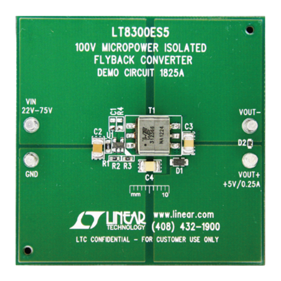
Demonstration circuit 1825A is an isolated flyback con-
verter featuring the
5.0V, and maintains tight regulation with a load current
from ~1mA to 250mA and over an input from 22V to 75V,
with a nominal 48V. The output current capability increases
with the input voltage.
The DC1825A needs a very small minimum load (~1mA) to
regulate the output voltage, thanks to the accurate current
limit capability and ultra low switching frequency of the
LT8300 at very light load. The standby input current of
the demo circuit is less than 400µA (typical) because of
the low quiescent current design of the IC and very small
minimum load requirement.
The Performance Summary table summarizes the perfor-
mance of the demo board at room temperature. The demo
circuit can be easily modified for different applications with
some pre-designed transformers.
performance summary
PARAMETER
Input Voltage
V
Quiescent Current
IN
Output Voltage
Maximum Output Current
Output Voltage Ripple (Peak to Peak)
Typical Switching Frequency
Minimum Switching Frequency
Efficiency
Arrow.com.
Downloaded from
100V
Converter with 150V/260mA Switch
LT
8300. This demo circuit outputs
®
CONDITIONS
I
= 0mA, V
OUT
V
= 22V – 75V
IN
I
= 1mA – 250mA
OUT
V
= 22V
IN
V
= 22V – 75V, I
IN
V
= 48V, I
IN
I
= 0mA
OUT
V
= 48V, I
IN
DEMO MANUAL DC1825A
Micropower Isolated Flyback
IN
The LT8300 is a simple-to-use high voltage monolithic iso-
lated flyback converter. No third winding or opto-isolator
is required for regulation. The part sets the isolated out-
put voltage with a single external resistor and integrates
compensation and soft start circuitry inside. Boundary
mode operation provides a small magnetic solution with
improved load regulation. Low ripple Burst Mode
tion maintains high efficiency at light loads while minimizing
the output voltage ripple. A 260mA, 150V DMOS power
switch is integrated along with all high voltage circuitry
and control logic into a 5-lead ThinSOT™ package.
The LT8300 data sheet gives a complete description of
the part, operation and application information. The data
sheet must be read in conjunction with this quick start
guide for DC1825A.
Design files for this circuit board are available at
http://www.linear.com/demo
L, LT, LTC, LTM, Linear Technology, the Linear logo and Burst Mode are registered trademarks
and ThinSOT is a trademark of Linear Technology Corporation. All other trademarks are the
property of their respective owners.
Specifications are at T
= 25°C
A
= 75V
IN
= 250mA
OUT
= 250mA
OUT
= 250mA
OUT
LT8300
®
MIN
TYP
MAX
22
48
75
400
4.75
5
5.25
250
50
330
8
80
opera-
UNITS
V
µA
V
mA
mV
kHz
kHz
%
dc1825af
1
Advertisement
Table of Contents

Related Manuals for Linear Technology DC1825A


Summary of Contents for Linear Technology DC1825A
- Page 1 Design files for this circuit board are available at some pre-designed transformers. http://www.linear.com/demo L, LT, LTC, LTM, Linear Technology, the Linear logo and Burst Mode are registered trademarks and ThinSOT is a trademark of Linear Technology Corporation. All other trademarks are the property of their respective owners.
- Page 2 DEMO MANUAL DC1825A Quick start proceDure The DC1825A is easy to set up to evaluate the performance 3. Check for the proper output voltages. The output should of the LT8300. Refer to Figure 1 for proper equipment be regulated at 5.0V (±5%).
- Page 3 DEMO MANUAL DC1825A Quick start proceDure Figure 1. Proper Measurement Equipment Setup INPUT OR OUTPUT CAPACITOR Figure 2. Proper Scope Probe Placement for Measuring Input or Output Ripple 5.00 = 48V 4.95 = 22V 4.90 = 22V 4.85 = 48V 4.80...
-
Page 4: Parts List
DEMO MANUAL DC1825A parts List ITEM REFERENCE PART DESCRIPTION MANUFACTURER/PART NUMBER Required Circuit Components CAP., X7R, 2.2µF 100V, 10% 1210 MURATA, GRM32ER72A225KA35L CAP., X5R, 100µF 6.3V, 20% 1210 AVX, 12106D107MAT2A CAP., X7R, 4700pF 1000V, 10% 1210 VISHAY/VITRAMON, VJ1210Y472KXGAT5Z DIODE, SCHOTTKY, 30V 1A PWRDI123 DIODES INC., DFLS130-7... - Page 5 Information furnished by Linear Technology Corporation is believed to be accurate and reliable. However, no responsibility is assumed for its use. Linear Technology Corporation makes no representa- tion that the interconnection of its circuits as described herein will not infringe on existing patent rights.
- Page 6 Linear Technology Corporation (LTC) provides the enclosed product(s) under the following AS IS conditions: This demonstration board (DEMO BOARD) kit being sold or provided by Linear Technology is intended for use for ENGINEERING DEVELOPMENT OR EVALUATION PURPOSES ONLY and is not provided by LTC for commercial use. As such, the DEMO BOARD herein may not be complete in terms of required design-, marketing-, and/or manufacturing-related protective considerations, including but not limited to product safety measures typically found in finished commercial goods.
Need help?
Do you have a question about the DC1825A and is the answer not in the manual?
Questions and answers