Advertisement
Description
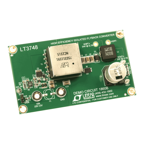
Demonstration circuit 1745A is an isolated flyback con-
verter featuring the LT3748 controller for high input voltage
applications. It is designed for a 15V output at up to 3A
from a 100V to 400V DC input. The part senses the iso-
lated output voltage from the third winding of the flyback
transformer during the off time of the power switch. No
opto-coupler or signal transformer is required for regula-
tion. A minimum load of approximately 150mA is required
on the output of the circuit to maintain regulation.
Optionally, the demo circuit can be powered from a uni-
versal offline input (85V~265V, 50/60Hz) using the AC
input terminals. Provisions for an EMI filter and surge
protection are provided in the demo circuit. The EMI filter
is designed to meet the EN55022 Class B standard. The
table below summarizes the performance.
The demo circuit can be easily modified for applications
requiring different output voltages/currents from either
an AC or DC input. Some pre-designed EFD25, EF16,
and EF25 transformers from vendors such as Würth
Electronics, Sumida, Pulse Engineering and Coilcraft can
perForMAnce sUMMArY
PARAMETER
Minimum Input DC Voltage
Maximum Input DC Voltage
Typical Start-Up DC Input Voltage Set by UVLO
Typical Shutdown DC Input Voltage Set by UVLO
Minimum Input AC Voltage
Maximum Input AC Voltage
Output Voltage, V
OUT
Output Current, I
OUT
Minimum Load Current with Regulated Output, I
Typical Efficiency with DC INPUT
Typical Efficiency with AC INPUT
Maximum Ripple Voltage, V
Maximum Switching Frequency at Full Load
Minimum Switching Frequency at Full Load
Arrow.com.
Downloaded from
(T
CONDITIONS
I
OUT
I
OUT
Line Frequency, 50Hz/60Hz
Line Frequency, 50Hz/60Hz
V
IN
V
IN
MIN
V
IN
V
IN
V
P-P
IN
V
IN
V
IN
DEMO MANUAL DC1745A
100V Isolated Flyback Converter
be assembled on the board. Some of these transformers
are listed in Table 1.
The LT3748 is a high input voltage isolated flyback con-
troller that eliminates the need for an optocoupler and
secondary-side reference voltage, all while maintaining
isolation between the primary and secondary-side with
only one part, the transformer, having to cross the isola-
tion barrier. The LT3748 is well suited for a wide variety
of industrial, automotive, medical, telecom, datacom
applications, where regulated isolated output is required.
The LT3748 datasheet gives a complete description of the
part, operation and application information. The datasheet
should be read in conjunction with this quick start guide
for Demonstration Circuit 1745A before powering the
demo circuit.
Design files for this circuit board are available at
http://www.linear.com/demo
L, LT, LTC, LTM, µModule, Linear Technology and the Linear logo are registered trademarks of
Linear Technology Corporation. All other trademarks are the property of their respective owners.
= 25°C)
A
= 3A
= 3A
= 100V ~ 400V (DC), I
= 150mA ~ 3A
OUT
= 100V ~ 400V (DC)
= 100V ~ 400V (DC), I
= 3A
OUT
= 85V ~ 265V (AC), I
= 3A
OUT
= 400V (DC), I
= 3A
OUT
= 400V (DC), I
= 3A
OUT
= 100V (DC), I
= 3A
OUT
LT3748
MIN
TYP
MAX
100
400
70
60
85
VAC (RMS)
265
VAC (RMS)
15 ±5%
3
150
87
84
750
155
55
dc1745afa
UNITS
V
V
V
V
V
A
mA
%
%
mV
kHz
kHz
1
Advertisement
Table of Contents

Related Manuals for Linear Technology DC1745A


Summary of Contents for Linear Technology DC1745A
- Page 1 AC or DC input. Some pre-designed EFD25, EF16, L, LT, LTC, LTM, µModule, Linear Technology and the Linear logo are registered trademarks of and EF25 transformers from vendors such as Würth Linear Technology Corporation. All other trademarks are the property of their respective owners.
-
Page 2: Performance Summary
Table (which is 100V for DC input). AND EVEN LIFE-THREATHENING INJURIES. CONTACT NOTE. Make sure that the input voltage does not exceed LINEAR TECHNOLOGY APPLICATIONS ENGINEERS FOR the maximum voltage specified in Performance Sum- PROPER COMPONENT REPLACEMENT. mary Table (which is 400V for DC input). Exceed this limit might damage the demo circuit. - Page 3 DEMO MANUAL DC1745A qUick stArt proceDUre of spec, make sure minimum load current is applied to 3. Turn on the power at the input. Increase the input volt- the output, the load is not set too high, and the current age to minimum as specified in Performance Summary of power supply is below current limit.
- Page 4 DEMO MANUAL DC1745A qUick stArt proceDUre Figure 1. Proper Measurement Equipment Setup for DC Input Figure 2. Proper Measurement Equipment Setup for AC Input dc1745afa Arrow.com. Arrow.com. Arrow.com. Arrow.com. Downloaded from Downloaded from Downloaded from Downloaded from...
- Page 5 DEMO MANUAL DC1745A qUick stArt proceDUre Figure 3. Proper Scope Probe Placement for Measuring Output Ripple Efficiency Regulation 15.05 15.00 14.95 14.90 14.85 14.80 = 100V = 100V = 200V = 200V 14.75 = 300V = 300V = 400V = 400V 14.70...
- Page 6 DEMO MANUAL DC1745A qUick stArt proceDUre = 500mA/DIV = 500mA/DIV = 500mV/DIV = 1V/DIV dc1745 F05a dc1745 F05b 500µs/DIV 500µs/DIV = 100V = 400V = 15V = 15V = 0.75A TO 1.5A = 0.75A TO 1.5A Figure 5. Transient with 0.75A to 1.5A at 100V and 400V Input...
-
Page 7: Parts List
DEMO MANUAL DC1745A pArts list REFERENCE PART DESCRIPTION MANUFACTURER/PART NUMBER Required Circuit Components CAC1,CAC2 Capacitor, 0.1µF , 250V/275VAC ECQ-UL, 20% Panasonic, ECQU2A104ML C1,CAC4 Nippon Chemi-Con, EKXG451ESS330MM20S Capacitor, 33µF , 450V, Size 18mm × 20mm, 20% Capacitor, FILM, 0.1µF , 400VDC, 10%... - Page 8 DEMO MANUAL DC1745A pArts list REFERENCE PART DESCRIPTION MANUFACTURER/PART NUMBER Resistor, 2.2Ω, 4W, 15% Murata, NTPA2R2LDNB0 Resistor, Chip, 34.0, 1%, 1206 Vishay, CRCW120634R0FKEA Resistor, Chip, 22k, 5%, 1210 Yageo, RC1210JR-0722KL Resistor, Chip, 6.04, 1%, 0603 Yageo, RC0603FR-076R04L R24,R25 Resistor, Chip, 510, 5%, 1210...
-
Page 9: Schematic Diagram
Information furnished by Linear Technology Corporation is believed to be accurate and reliable. However, no responsibility is assumed for its use. Linear Technology Corporation makes no representa- tion that the interconnection of its circuits as described herein will not infringe on existing patent rights. - Page 10 Linear Technology Corporation (LTC) provides the enclosed product(s) under the following AS IS conditions: This demonstration board (DEMO BOARD) kit being sold or provided by Linear Technology is intended for use for ENGINEERING DEVELOPMENT OR EVALUATION PURPOSES ONLY and is not provided by LTC for commercial use. As such, the DEMO BOARD herein may not be complete in terms of required design-, marketing-, and/or manufacturing-related protective considerations, including but not limited to product safety measures typically found in finished commercial goods.
Need help?
Do you have a question about the DC1745A and is the answer not in the manual?
Questions and answers