Table of Contents
Advertisement
Quick Links
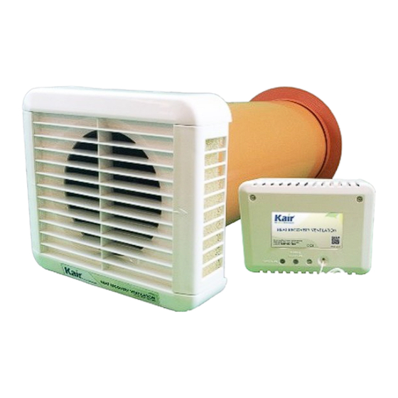
Kair Single Room
Heat Recovery Ventilator
Model:
KHRV150/12RH - Pullcord & Humidistat
KHRV150/12PC - Pullcord
INSTALLATION & MAINTENANCE INSTRUCTIONS
Please read and save these instructions
Included items
Description
Through Wall unit
Transformer
& humidity sensor
Blanking Plate (optional)
Wall Mounting Screws
Rawplug
Tamperproof Screws
For unit and transformer
- require KTMPB to use
Installation and Maintenance
instructions
User Guide
www.kair.co.uk
Contents
Qty
Page
x1
1
x1
2
3
x1
4 & 5
x6
6 & 7
7
x6
8
8, 9 & 10
10
x7
(optional)
11
x1
x1
Content
What am I?
Advertisement
Table of Contents

Related Manuals for Kair KHRV150/12RH


Summary of Contents for Kair KHRV150/12RH
-
Page 1: Table Of Contents
Kair Single Room Heat Recovery Ventilator Model: KHRV150/12RH - Pullcord & Humidistat KHRV150/12PC - Pullcord INSTALLATION & MAINTENANCE INSTRUCTIONS Please read and save these instructions Contents Included items Description Page Content Through Wall unit Safety First Isolating Transformer (Humidity sensor unit). -
Page 2: Safety First
Safety First The Heat Recovery Ventilator is a “SELV” (Safety Extra Low Voltage) ventilator that operates at 12 volts AC. Under no circumstances must this be connected directly to the mains supply. Damage so caused is not covered by the warranty. The isolating transformer / humidity sensor supplied must provide the low voltage used by the ventilator. -
Page 3: Transformer/Humidity Sensor Unit
Transformer/Humidity Sensor Unit LOW VOLTAGE OUTPUT MAINS INPUT SELECT EITHER SLOW OR FAST SPEED WITH 5AMP QUICK BLOW FUSE. (See page 7) FACTORY SEALED DO NOT ADJUST LIGHT LEVEL SENSOR TRANSFORMER ADJUSTMENT (See Page 8) HUMIDISTAT MODEL ONLY THUMB WHEEL HUMIDITY LEVEL ADJUSTER (See page 1) PULL CORD SWITCH MAINS LED... -
Page 4: Installation
Installation You should site the ventilator close to the The ventilator is designed to be installed ceiling. This will ease the installation of the using a 6” (152mm) Core Drill system. power cable and give you the best position for air circulation. The hole needs to be angled downwards very slightly to a maximum of 1.5 or 8mm... -
Page 5: Inside Installation Of The Finisher Ring
Inside installation of the finisher ring Proceed as follows: Push the large tube through the hole so it extends some 50mm beyond the face of the outside wall. Apply adhesive around the rear face of the split ring – do not compress the adhe- sive. - Page 6 Installation - Continued Mounted on the heat exchanger is a round plastic baffle that secures the air intake filters. The extraction fan adjacent to these filters goes to the outside wall. Use the PVC weld adhesive to stick the small tube you have cut to length onto the end flange of the extract fan and allow the adhesive to set.
-
Page 7: Location Of The Transformer/Humidity Sensor Unit
Location of the Transformer/Humidity Sensor unit The Transformer / Humidity sensor unit may be mounted on the wall or ceiling. Note: This part must not be mounted in the interior of a bath tub or shower basin and must be positioned out of Position the transformer / humidity unit reach of a person using a fixed bath or at least 6”... -
Page 8: Transformer/Humidity Sensor Unit Wiring
Location of the Transformer/Humidity Sensor unit - 2 Follow the line diagram below to make the correct connections between the fan assembly and the transformer/humidity sensor, and wall plate. Place the fan assembly and front cover through the wall plate and push home. Apply power to the system and check operation. -
Page 9: Light Level Sensor
Light Level Sensor A Light Level Sensor is included to prevent the fan from switching automatically to boost at nighttime. This is a useful feature particularly if the Heat Recovery Ventilator is installed in a bedroom or bed-sit accommodation, ensuring noise is kept to a minimum. The sensor is factory set in the OFF position as this is preferred for most installations. - Page 10 Front Facia Extract Filters: Isolate the fan unit from the mains supply before commencing this procedure and wait for the fan blades to stop rotating. Open the grille flaps on both sides of the unit front facia grille. Open the filter covers by gently pulling each cover in the direction marked by the arrow.
- Page 11 Internal Rear Intake Filters - Continued Now the main fan unit is ready to be inserted back into the wall, ensure that the vital outer cowl assembly and 125mm separator tube (required for installation in walls which exceed 225mm depth) are still secured. Ensure that the fan unit is inserted the correct way up so that the electrical connection/terminal block will be made properly and that the front filter covers (if not already fixed) are located prior to the unit being ‘pushed home’...
-
Page 12: Registration
08451 66 22 50 Web: www.kair.co.uk Email: info@kair.co.uk Address: 6 Chiltonian Industrial Estate, Manor Lane, Lee, London SE12 0TX As part of our policy of continuous product development, Kair reserves the right to alter specifications without notice. Page Version: 20130731...
Need help?
Do you have a question about the KHRV150/12RH and is the answer not in the manual?
Questions and answers