Table of Contents
Advertisement
23852973
Specifications
Parameter
Specifications
Voltage
10-30 VDC; 12-24VAC
Requirements
Keypad Current
VDC
Requirements (Max)
10V: 85mA
30V: 115mA
Relay Contact Rating 2A @ 30VDC (Main & Aux)
REX Input
Normally Open Dry Contact
Door Position Switch
Normally Closed Dry Contact
Input
Mechanical
4.50" H x 2.75" W x 0.60" D
Dimensions
Environment
Indoor or Outdoor
Temperature
-31°F to 151°F (-35ºC to 66°C)
Tolerance
Front End Cable
Stranded and Shielded
Type
Front End Distance
1000 Ft. – 18AWG; 500 Ft – 20 AWG; 250
and Wire Gauge
Ft. – 22 AWG
Firmware Version
1.0x ("1" is the major version; "0" is the
minor version; "x" is a minor version,
reserved for bug fixes, which is indicated
with a letter, such as "a".)
Keypad Operating Modes
The KP2000E/EM Series keypad has two operating modes:
Standalone Mode and Wiegand Front End Mode. Below is a brief
explanation of each mode. Refer to the programming section for
details about selecting each mode.
Standalone Mode:
By default, the keypad is programmed for Standalone Mode. In this
mode, all the users and other programming options are maintained
within the keypad and no additional controller is required. The lock
and all other inputs and outputs are connected directly to the keypad.
Wiegand Front End Mode:
In Wiegand Front End mode, a separate UL Listed compatible
Wiegand Access Control panel is required. When you enter a code on
the keypad it is then sent to the control panel as Wiegand card data,
depending on which format you've programmed it for. The control
panel maintains the users and programming options and makes all
the access control decisions. The locking device and all inputs and
outputs are connected to the control panel.
KP2000E/EM Series Style Keypad
Installation and Programming Instructions
Models KP2000EXX and KP2000EMXX
VAC
12V: 150mA
24V: 200mA
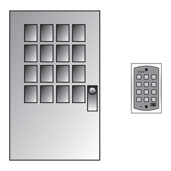
Mounting the Keypad
The keypad is designed to be flush mounted using a standard UL
Listed single-gang electrical box. Mounting height can vary depending
on requirements. An appropriate range is typically between 48 and 52
inches on center off the floor.
For outdoor installations, use a UL Listed weatherproof back box and
seal the wire entry locations with silicone and provide a drain hole.
For additional protection, install the provided foam gasket between
the keypad and the back box. In addition, use the anti-oxidant grease
pack for the wire harness connectors.
Circuit Board Diagram
J3
1
Note: J3 is NOT USED
48 - 52"
J2
1
Aux
Main
Relay
Relay
1
P2
Advertisement
Table of Contents

Subscribe to Our Youtube Channel
Related Manuals for Schlage KP2000EM Series


Summary of Contents for Schlage KP2000EM Series
- Page 1 KP2000E/EM Series Style Keypad Installation and Programming Instructions 23852973 Models KP2000EXX and KP2000EMXX Specifications Mounting the Keypad The keypad is designed to be flush mounted using a standard UL Parameter Specifications Listed single-gang electrical box. Mounting height can vary depending on requirements.
- Page 2 Main Wire Harness (P2) UL Requirements The KP2000E/EM Series keypad is a UL Listed access control unit. This section contains information regarding the requirements necessary to meet UL compliance. Wiring methods shall be in accordance with the National Electrical Code (ANSI/NFPA70), local codes, and the authorities having jurisdiction.
- Page 3 Wiring a Maglock (Fail-Safe) Shunting a Normally Closed Zone 1. Connect the red wire (V+) to the blue wire (common), and then 1. Connect the blue wire (common) to the common connection on the connect them to the positive on the power supply. door position switch.
-
Page 4: Programming Users
Wiegand Front End Wiring Diagram Selecting Standalone Mode To use the keypad as a Wiegand Front End, connect the red, black Standalone Mode is the default operating mode. If you’ve changed the white/black, white/yellow and brown wires on the main keypad wire operating mode and want to revert back to Standalone Mode, use the harness to the corresponding terminals on the UL Listed compatible following steps:... - Page 5 User Types Assigning Outputs (Standalone Mode Only) (Standalone Mode Only) Command/Action Keys to Enter/Details User Types Description Assign Outputs 10 # virtual output # physical Toggle User A toggle user latches the Lock Output like an output # ** on/off switch. When you enter the code the first Virtual Outputs Physical Outputs time, the Lock Output is activated and remains...
-
Page 6: Programming Keypad Options
Programming Output Times Programming Keypad Options (Standalone Mode Only) (Default settings are in bold) Command/Action Keys to Enter/Details Command/Action Keys to Enter/Details Change Lock Output Time 11 # time # 0 # ** (1-255 sec) Change Keypad Options 30 # option # setting # ** Set OUT2 Time Duration 12 # ttt # mmm # ** Option... - Page 7 Programming Keypad Parameters Wiegand Data (Default settings are in bold) When the keypad is configured in Wiegand mode, the keypad data is sent as a complete Wiegand data packet, as though you presented a Command/Action Keys to Enter/Details card. Change Keypad Parameters 32 # parameter # value # ** Parameter Value...
- Page 8 Performing the Keypad Self-Test Programming Wiegand Front End Mode After installing the keypad, Schlage recommends that you perform Options the keypad self-test once a year to ensure that the keypad is working This section contains programming commands that apply only to properly.
Need help?
Do you have a question about the KP2000EM Series and is the answer not in the manual?
Questions and answers