Advertisement
Quick Links
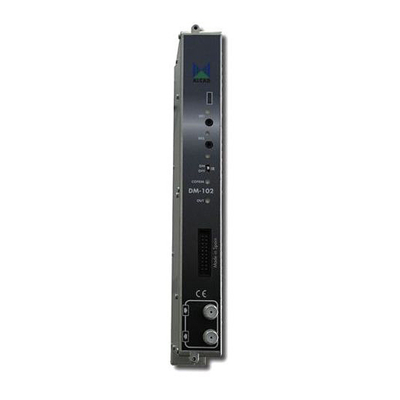
Technote10: Setting up DM-102 COFDM Modulators with PS-011
DM-102 is a fully agile Digital Modulator which is designed to convert 2 AV
signals into a digital modulated channel.
Power Supply
IMPORTANT: Layout of the modules must be as shown above. Power Supply (FA-312) must
be located on the far left hand side and launch amplifier (PA-720) must be the next module in
the chain. Please look at the layout above. A limit of 6 DM-102 modules can be powered by
one FA-312. If FA-310 is being used only 3 modules is the limit due to power consumption.
AIM PROGRAMMER TO IR SENSOR LOCATED ON EACH DIGITAL
MODULATOR WHEN PROGRAMMING
Programming of Modules
Ensure the following prior to programming:
• It is necessary to connect all the modules to the support frame SP-226 (code 9120130)
for the system to function.
• It is also recommended that you make the earth connection to the building using a cable
with a section of at least 4 mm.
• Ensure that you have the Alcad programmer PS-011 with firmware version 1.11 or
later.
• Power supply/Control cable must be plugged into each module.
REMOVE
modules without disconnecting mains supply power from wall outlet. Always
disconnect the equipment, and then reconnect it to the mains supply. Failure to do so
can cause equipment to fail.
Launch Amplifier
1
IR Sensors
DO NOT ADD OR
Advertisement

Related Manuals for Alcad DM-102


Summary of Contents for Alcad DM-102
- Page 1 (PA-720) must be the next module in the chain. Please look at the layout above. A limit of 6 DM-102 modules can be powered by one FA-312. If FA-310 is being used only 3 modules is the limit due to power consumption.
- Page 2 OPERATION OF PS-011 PROGRAMMER...
- Page 6 “OFF” position. The programming indicator light will go out. To start programming the DM-102 module you desire to programme please slide the programming indicator switch to the ON position.
- Page 7 Once you have scrolled the selection bar to the modulator press the button to take you to another window which can be seen below Press the button to take you to “Output” configuration screen which can be viewed below...
- Page 8 The next two options ‘Channel table’ and ‘Channel’ will be locked and not applicable if the setting ‘Program by Frequency’ has been selected on the last option as per ALCAD recommendation.
- Page 9 DIGITAL FREQUENCIES FOR AUSTRALIA ARE HIGHLIGHTED IN YELLOW Press transmit button on the programmer to send the change through to module.
- Page 10 Attenuation is the dropdown box that allows you to adjust the power level output of the modulator. Press transmit button on the programmer to send the change through to module. Offset is the dropdown box that gives you the option to add or subtract either 0.166 or 0.125MHz of the output digital RF frequency.
- Page 11 FEC (forward error correction) has 5 option rates. All broadcast systems transmitting data will suffer errors. In order to correct these errors various forms of error correction are used. The rate at which this is done affects the rate at which the data can be transmitted. The higher the level of error correction that is applied, the greater the level of supporting error correction data that is needed in order to be transmitted.
- Page 12 Please note the following screenshot and settings: AV Input 2 AV Input 1 ACTIVE- To enable the input to be active the option must be set to “ON”. If you do not want the input to be seen or is not going to be used set to “OFF”. Press transmit button on the programmer to send the change through to module.
- Page 13 ADVANCED – The ADVANCED menu option needs to be set to enable PID and bitrate configurations for Video and Audio. Name of the network you want the signal to be broadcast to Service Provider - This name entered needs to be used on all modulators that are on this same network.
- Page 14 Audio PID- This value should ALWAYS be one value increment of the Video PID that was entered. Thus if you have set 105 for the Video PID then you should set 106 for the Audio PID. Press transmit button on the programmer to send the change through to module. Audio bit rate –...
- Page 15 Press the down arrow to take you to the next window of parameters that need to be set. Please set these settings to your liking. Press transmit button on the programmer to send the change through to module on each parameter that has been changed.
- Page 16 Once you have entered name you desire press okay and enter module number 1. This name must also be unique. Each modulator configuration settings file should be called a different name e.g. Quest 1. Press OK and you are given confirmation of your saving of the configuration file as can be seen below.
- Page 17 Press the OK button and you will be taken to the Channel Numbering (LCN) window. Look at screenshot below which shows the program names of the modulator you are setting the LCN for. Service Name of AV Input 2 Service Name of AV Input 1 LCN Number is the channel...
- Page 18 NIT to the modulator. Successful completion of the NIT transmission is confirmed by the programmer with the green tick on the window. You have now successfully programmed the DM-102 modulator. If you are still experiencing problems with programming, please contact ALCAD technical support on 03 9720 5329.
Need help?
Do you have a question about the DM-102 and is the answer not in the manual?
Questions and answers