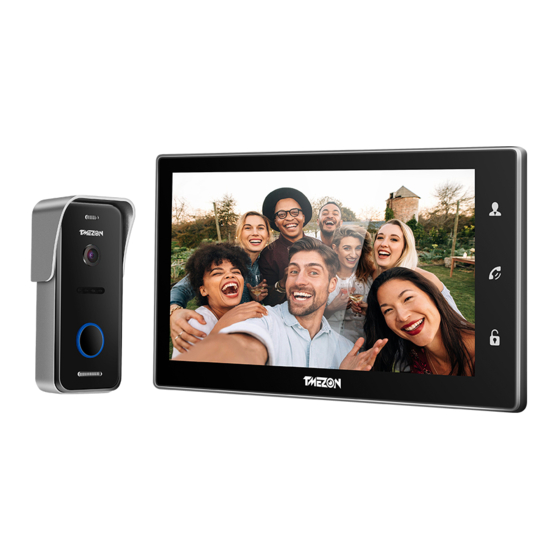
TMEZON MZ-IP-V103W Operation Instruction Manual
4-wire ip video door phone 10'' touch screen series
Hide thumbs
Also See for MZ-IP-V103W:
- Operation instruction manual (39 pages) ,
- Wiring diagram (13 pages)
Table of Contents
Advertisement
Statement
* If there is any doubt or disputable regarding information in this manual, you can call our company for
clarification.
* There maybe some differences between the descriptions provided here and the actual devices, as our
products are constantly developing and upgrading. We apologize if this manual does not contain all of the
latest updates.Thanks.
Please scan this QR code to
watch the installation video
MC-1524 A-1
4-Wire IP Video Door Phone
10'' Touch Screen Series
User Manual
Advertisement
Table of Contents

Related Manuals for TMEZON MZ-IP-V103W


Summary of Contents for TMEZON MZ-IP-V103W
- Page 1 4-Wire IP Video Door Phone 10'' Touch Screen Series User Manual Please scan this QR code to watch the installation video Statement * If there is any doubt or disputable regarding information in this manual, you can call our company for clarification.
-
Page 2: Limitation Of Liability
※ LIMITATION OF LIABILITY The doorbell/camera units should be fitted with an approved weather shield if the chosen position is in direct sunlight, or in contact with rain, snow or irrigation sprinkler systems. ※ This users' manual is supplied 'as is', with no warranties, be it expressed or implied, including, ※... -
Page 3: Table Of Contents
Table of Contents Table of Contents 2.4.6 Maintenance ..................27 LIMITATION OF LIABILITY..................1 2.4.6.1 SD ....................27 DISCLAIMER OF WARRANTY................1 2.4.6.2 Upgrade ................... 27 SAFETY INSTRUCTIONS..................1 2.4.7 User ....................28 CARING FOR THE ENVIRONMENT BY RECYCLING..........2 2.4.8 Default ....................30 COPYRIGHT STATEMENT..................2 2.4.9 Information .................. -
Page 4: Fitting For The Indoor Monitor
1. Description Of The Indoor Monitor 1.3 Wiring Diagram For IP 10’’ touch screen series, users can connect up to two AHD outdoor doorbells, or two 1.1 Fitting for the Indoor Monitor AHD CCTV cameras, or two D1 analog outdoor doorbells, or two D1 CCTV cameras, and three extendable traditional indoor monitors(video door phone) one by one to the For IP 10’’... -
Page 5: About Extension Cables
About Extension cables Cat5,cat6 network extension cables We don’t provide the extension cables in the box. You can use the RVV4(4 core cable) or cat5/cat6 to extend Cat5, cat6 network cable the distance between the monitor-doorbell,monitor-monitor, Cut the RJ45 port. or doorbell-doorbell. -
Page 6: Installation Process Of Indoor Units
To install the indoor unit , please follow these steps as below: Please note the silk printing marked on PCB in order to avoid incorrect connecting. Surface mount The wiring connection requirement: Connection cable 1. 4C ordinary non-STP wiring cable; Screw anchors Bracket 2. -
Page 7: Operation Introduction
◆ Note: MONITORING The back-light of each button will be on when user presses any button or some visitor calls on the outdoor doorbell. The back-light of each button will be off if user doesn’t do any operate on the Please be aware of Connection of 2 outdoor cameras to 1 indoor monitor is required for dual device in 10 seconds. -
Page 8: System Settings For Indoor Units
◆ CALL TRANSFER TO OTHER EXTENSION 2. System Settings For Indoor Units At least 2 indoor units is required Note: 1. This indoor monitor supports touch screen function. In standby mode, touch on the Outdoor camera call indoor NOTICE: monitor and conversation When you are transferring a call to other extension, the original screen to display channel views, and slide finger in any direction to bring up the menu is underway... -
Page 9: Tool Bar
indicates that there was recording on the day. Click any date in this frame to search by the 2.2 Tool Bar recording files of that day, and the search results will be shown in the file frame. On the file list, Slide finger in any direction or single-click the right-hand mouse button, and it will display the “Channel”... -
Page 10: Channel Status Display
or D1. “HD” means that user can connect up to two AHD cameras to the indoor monitor. “D1’’ means 2.3.7 Channel status display that user can connect up to two D1 cameras to the indoor monitor. The following status icons will appear in the lower left corner of each channel frame. [CVBS Out]: From this field, select the mode connected to the extendable indoor monitor, i.e. -
Page 11: Door
2.4.2 Door [Video Margin] Click “ ” to enter the “Video Margin” menu, the entire video screen can be moved up, down, Left-click/touch the “Door” icon to enter the “Door setting” menu. Door setting includes: “Basic”, to the left, and to the right using this option. and “Ring”. -
Page 12: Network
[Media Port]: Port for the private protocol of the device and computer; the default is “9000”. If [Door2 Ring]: From this field, to set up the ring tone of Door2, a total of 16. this port is being used by other server, use another free port for the device. [Volume]: From this field, to set up the volume of the ring, values can be set from 0 to 20. -
Page 13: Record Scheduling
Wifi Wifi Sub stream dlink Password TP-LINK_169CE6 57/100 123456789 Channel dlink 57/100 TL-WR941N 42/100 Frame rate Bit rate 128K Bit rate control 1) Click/touch “ ” and available wireless devices will be shown on the list. Choose one and click/touch it, if the wireless password of the wireless router is enabled, it pop-up a window to enter the password of the wireless router, input the correct password and setting ok, the indoor device will reboot automatically, it will be connected to the wireless router after starting. -
Page 14: Alarm
To enter motion setup, the dialog window where Sensitivity, MD Area, Enable Switch, record To set up weekly schedules, click/touch on the box of the recording status to be used (Alarm, settings and Push Switch can be set will appear. Normal, or No record) and then click/touch on each box in the schedule time-line that this [Channel]: In this field, select the channel to be set up. -
Page 15: Maintenance
System maintenance I/O status types: Upgrade Open: set the I/O to “open”, by default NO(Normally open), it means that in its normal state, the sensor is kept under constant low voltage. If the output voltage changes from low to high, System upgrade then the alarm will be triggered. -
Page 16: Default
[Remote Permission]: This is a very important function for remote operation of the indoor [Delete Users]: From this window (see the following figure), the Administrator can delete monitor. The Administrator can use this function to set each user's remote access permissions, users (the color of the user has been selected will be yellow) by selecting the user of the user such as access to Playback/Download, Set Parameters and PTZ Control from a computer that account to be deleted. -
Page 17: Save/Exit
2.4.10 Save/Exit Home Security Begins at the uCareHome On the “Configuration” menu, right-click or click/touch “ ” to enter the “Save” menu. Save Your new security products are start of uCareHome around your entire property. Now, you’ll always be connected to your home, so you can watch over your property and answer it from anywhere. Save Exit [Save]: Save all settings and exit the menu. - Page 18 3. Set up IP Indoor Monitor 1.Download uCareHome app Step 1. Login the uCareHome app The uCareHome will walk you through setting up and managing your all security products. Search for “uCareHome” in one of the app stores, android in “Play Store”, and IOS in “App Store”. 2.WiFI setting Note: 1).
- Page 19 Step 4. Connect to indoor monitor hotspot Step 6. Add the indoor monitor a. For android, it can be connected to the indoor monitor hotspot automatically. Name b. For IOS, you need connect manually. is the device name for your IP indoor monitor. Password is the device password for login your IP indoor monitor.
- Page 20 3.1 The icons on live view 3.2 Add Existing Device Quality switch:HD/SD Name is the device name for your IP indoor monitor. Snapshot Password is the device password for login your IP indoor monitor. The default password is "888888". Record/Stop record Adjust volume of speaker/Microphone Video full screen display Connect/disconnect view...
-
Page 21: Reset
3.5 Push Mode 3.3 System Setting Home mode is turn off all devices push function. Away Mode is turn on all devices push function. app system default is away mode. Custom Mode to optional control device push function. 3.6 Account Media Lock Time local storage. -
Page 22: Web Browser Operation
* Run ActiveX controls and plug-ins. 3. Web Browser Operation * Script ActiveX controls safe for scripting. Prompt: Before setting up remote access, turn Disable the firewall and any anti-virus software 3.1 Feature currently running on the computer. Install the software through the Internet browser of OS to conveniently operate the network from a remote location. -
Page 23: Control Download And Installation
Select the English interface from the upper left side. Enter the correct password if a password has been enabled. The password is the same as the one set in indoor unit. Step 5: Examine the IP address, subnet mask, and default gateway on the PC. [USER ID]: In this field, enter the username. -
Page 24: Controls
The left bottom corner of each individual channel is occupied by camera view tools: : Connect the current window view or close the current window view. :Start recording or stop recording of the current channel view. And the right bottom corner of the current channel has a normal recording video symbol “... -
Page 25: Toolbar Guide
B. Alarm Settings Double-click one of the listed recorded videos or select one of the listed recorded videos and then click “PLAY” to begin playback. From the sidebar on the left, click “Alarm Setting”, then select “Channel Alarm” to enter the “Channel Alarm”... -
Page 26: Local Settings
H. REMOTE UPGRADE E. IP Firewall From the sidebar on the left, click “REMOTE UPGRADE” to enter the remote upgrade interface. From the sidebar on the left, click “Network Setting”, and then select ”IP Firewall” to enter the Clicking “ ”... -
Page 27: Logout
3.5.8 logout Press “LAN Search”: Click “Logout” to log out of the system. 4. Mobile Phone Software Visit This IP video door phone can transmit live feed to your mobile phone, so that you can have 'on the go' access to your surveillance system from virtually anywhere. To view, you must install a mobile operating system specific program into your mobile. -
Page 28: Appendix 1. Accessing The Indoor Unit Via Mozilla Firefox
5. Select “Allow” to download multiple files and the following screen will appear. Appendix 1. Accessing the indoor unit via Mozilla Firefox 1. First, install Firefox on Windows(This document will use Firefox 3.6 as an example ) 2. After installing Firefox, search for the “IE TAB” add-on for Firefox; this file is named “ie_tab_plus-1.95.20100930-fx+sm (IE Tab Plus (FF 3.6+).xpi”. -
Page 29: Appendix 3.How To Ensure Reliable Remote Viewing Of The Indoor Device Through Ie Browser On Win7/Win8 64Bit Os
Appendix 3. How to ensure reliable remote viewing of the D. To change Compatibility View settings 1) Open Internet Explorer in the desktop. indoor device through IE browser on Win 7/Win 8 64bit OS 2) Press the Alt key to display the Menu bar (or press and hold the Address bar and then select Menu bar). -
Page 33: Contact Us
Contact us Manufacturer:Zhuhai Tmezon Technology Co.,Limited ADD: No.6.Pingbei 2nd.Rd,Nanping Science and Technology Industrial Community, Zhuhai City,Guangdong,China Official Website: http://www.tmezon.com Technical Support: support@tmezon.com...
Need help?
Do you have a question about the MZ-IP-V103W and is the answer not in the manual?
Questions and answers