
Related Manuals for Ametek Land 4500 MKIII


Summary of Contents for Ametek Land 4500 MKIII
- Page 1 4500 MKIII USER GUIDE PUBLICATION N 804546 LANGUAGE: ENGLISH Model 4500 MkIII Q U A L I T Y C U S T O M E R S O L U T I O N S...
- Page 2 IMPORTANT INFORMATION - PLEASE READ Health and Safety Information Read all of the instructions in this booklet - including all the WARNINGS and CAUTIONS - before using this product. If there is any instruction which you do not understand, DO NOT USE THE PRODUCT.
- Page 3 Web: www.landinst.com For further details on all AMETEK Land offices, distributors and representatives, please visit our websites. Return of Damaged Goods IMPORTANT If any item has been damaged in transit, this should be reported to the carrier and to the supplier immediately.
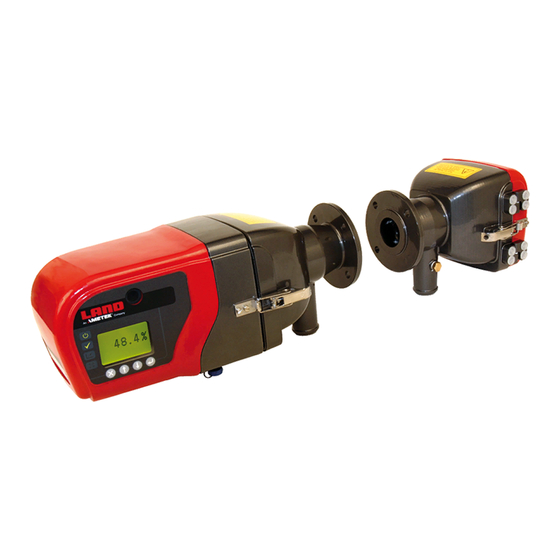
- Page 4 Model 4500 MkIII Opacity and Dust Monitor Blank Preface User Guide...
-
Page 5: Table Of Contents
Locking the Fail-Safe Shutter Open Upgrading the 4500 MkIII Transceiver Firmware Replacement Parts and Consumables E-13 Changing the Installation Pathlength on a Model 4500 MkIII Set the correct focus Align and Calibrate the Model 4500 MkIII Set the B constant... -
Page 6: A Introduction
INTRODUCTION... -
Page 7: A1 General Description
The Land Instruments International Model 4500 MkIII Continuous Opacity Monitoring System (COMS) measures opacity by shining a light beam through flue gases. An internal microprocessor calculates dust density and other parameters. The Model 4500 MkIII is designed for continuous operation in all weather conditions. Maintenance requirements are minimal. Transceiver Containing all of the major electronic and electro–optic components. - Page 8 The output can be set to ‘TRACK’ or ‘HOLD’ the measurement signal during calibration routines. If ‘TRACK’ is set, the measurement signal will continue to be output during calibration. If ‘HOLD’ is set, the measurement signal will remain at the last recorded reading before calibration, until the calibration routine is complete. Relay Outputs Located on the key panel of the 4500 MkIII are three LEDs which light to indicate the operation of the following relay outputs: SYSTEM OK CALIBRATION ALARMS Computer Interface Operation The Model 4500 MkIII Dust and Opacity Monitor may be connected to a computer or data acquisition system via its RS485 Modbus interface.
-
Page 9: A2 Installation Diagram
Opacity and Dust Monitor Model 4500 MkIII A2 Installation Diagram Typical Model 4500 MkIII Dust Opacity Monitoring System, showing all components installed. Fail-Safe Shutter Fail-Safe Shutter (Optional) (Optional) Transceiver Retro-Reflector Mounting Flanges Air Purge Blower Air Purge Blower AFU-APS-I/O Control Room Unit (Optional) symbol pqrs wxyz User Guide A - 3... -
Page 10: A3 Installation Instructions
Model 4500 MkIII Opacity and Dust Monitor A3 Installation Instructions CAUTION If the blower is not supplied through an APS (as described in Section A4), an external isolator, incorporating over-current protection, must be fitted to the blower supply. CAUTION The purge air supply must be connected and working before the Transceiver and the Retro-Reflector are installed. A3.1 Installation Checklist Select the installation location. - Page 11 Opacity and Dust Monitor Model 4500 MkIII A3.2 Selecting an Installation Location The location of the mounting flanges may be affected by the type of Air Blower Unit(s) to be used. Please refer to the Air Blower Unit manual. For new plants, the location of the Transmissometer should be planned during the design stages. For existing plants, it is critical that the best...
- Page 12 Model 4500 MkIII Opacity and Dust Monitor A3.3 Maintaining the path length during installation The installation path length is defined as the distance between the outer faces of the mounting flanges of the transceiver and retroreflector. This is somewhat greater than the stack flange-to-flange path length, to allow for optical alignment. The length of accessories such as spoolpieces or fail- safe shutters also increases the installation path length relative to the stack flange-to-flange path length. The installation path length must be specified at the time of order and the instrument is factory set for this path length.
- Page 13 Opacity and Dust Monitor Model 4500 MkIII Position the Transceiver mounting flange with the “TOP” label in the 12 o’clock position and tack weld the mounting flange in place. Accurate positioning of the flange at this stage is critical to the operation of the instrument. If the flange is not parallel to the stack wall it will be impossible to align the instrument correctly.
- Page 14 Model 4500 MkIII Opacity and Dust Monitor A3.5 Mounting Details Air Purge Mounting Holes The air purge unit must be fixed to the mounting flange. It has three mounting holes to accept the mounting studs from the Standpipe. Mounting holes 130 mm (5 ⅛”) Front view of Air Purge showing mounting holes A - 8 User Guide...
- Page 15 Opacity and Dust Monitor Model 4500 MkIII User Guide A - 9...
- Page 16 Model 4500 MkIII Opacity and Dust Monitor 5. NOTE: CHECK THAT EACH MOUNTING STUD HAS SIX PAIRS OF SPRING WASHERS Installing a 4500 MkIII on existing 4500 series mountings A - 10 User Guide...
- Page 17 Opacity and Dust Monitor Model 4500 MkIII A3.6 Using the Flange Alignment Tool The flange alignment tool (part number 703.070) consists of two plates which are mounted on to the flanges. One plate supports a light source, the other a small telescope with a target in the centre. When the flanges are properly aligned, the light spot is located in the centre of this target. Light source Alignment circle The flange alignment tool is used as follows: Remove the washers from the mounting flanges. Retain these as they are essential to the correct installation of the instrument. Tack weld the flanges in position. Mount the flange alignment tool as shown below, with the light source attached to flange 2. Align flange 1 and weld it into place. Remove the alignment tool and refit it with the light source attached to flange 1. Align flange 2 and weld it into place. Replace the washers. See section A3.8. Light source Reinforcement if required Flange 2 Flange 1...
- Page 18 Model 4500 MkIII Opacity and Dust Monitor A3.7 Important information for installing the transceiver and retro-reflector INSTALLATION PATHLENGTH 446 (17.56) 235 (9.25) 128 (5.04) 128 (5.04) 4500 MkIII 4500 MkIII Transceiver Retroreflector Standard stand pipe Land Part Nº 703.020 MINIMUM SWING RADIUS MINIMUM SWING RADIUS Check the dimensions carefully before installation. Allow at least 1 m (3.3 ft) for mounting and removal procedures Allow a minimum of 200 mm (8 in) directly below the instrument for purge air (3) and electrical connections (4).
- Page 19 Opacity and Dust Monitor Model 4500 MkIII A3.8 Mounting the Transceiver and Retro-Reflector Ideally, the instrument should be installed when the process is not operating and the stack is cold. The air blower unit should be operating and connected to the Transceiver and Retro-Reflector before the instrument is mounted on to the flanges. Check that each mounting stud has the correct number of spring washers (5) arranged as shown - these may have been removed if the flange alignment tool was used. The standard flange 703.020 has four...
- Page 20 The 4500 MkIII requires a 24 V dc 3A supply. Current consumption is 0.25 A at temperatures above -20 °C. Current increases to 3 A at lower temperatures, when the case heaters are operating. Signal Connections Transceiver data cables (See diagrams in A3.10) Lightning Protection The 4500 MkIII opacity monitor is installed frequently in locations exposed to lightning strikes. The instrument’s susceptibility to lightning-induced damage can be greatly reduced by connecting the grounding point to a reliable ground (earth) connection via a copper braid. The grounding point is shown in the photograph below. Grounding Point A - 14...
- Page 21 Opacity and Dust Monitor Model 4500 MkIII System Electrical Connections Overview User Guide A - 15...
- Page 22 Model 4500 MkIII Opacity and Dust Monitor A3.10 Transceiver Connections Connector B (Male) Connector C (Female) Connector A (Male) Connector A Colour Function Pin Nº +24 V dc Blue Screen Screen Connector B Pin Nº Colour Function In Cal Relay NO...
- Page 23 Opacity and Dust Monitor Model 4500 MkIII A3.11 Cable Specification Cable types recommended by LAND. Electrical Core Core Size Core Nº of Supplied Connections Size strands/ Size Diameter Screened Cores Overview 16/0.2 6.5 mm LAND 0.25 7/0.2 6.1 mm LAND 0.25 7/0.2 6.1 mm LAND 0.5 to...
- Page 24 Model 4500 MkIII Opacity and Dust Monitor A3.12 Installation with a Fail-Safe Shutter (FSS) The Fail-Safe Shutter provides protection to the optical system in the event of a short-term purge failure. It opens when power is applied and closes on loss of power, or if it receives a signal from the AFU. When used with a 4500 MkIII, the shutter closes each time the instrument performs an automatic zero calibration. This function reduces the risk that the shutter will jam in the open position and fail to close when needed. The instrument gives an error message if the shutter does not close and open as expected. The shutter is not designed to withstand extended exposure to stack gases, and such exposure will cause permanent damage. Depending on the...
- Page 25 Opacity and Dust Monitor Model 4500 MkIII A3.13 Replacing a 4500 MKII or 4500 MkII+ incorporating a Fail-Safe Shutter If the 4500 MkIII is replacing an older 4500 MkII or MkII+ and a fail-safe shutter is used, you will need to use a special Adaptor Kit (Part Nº 811013). To complete the installation, refer to the instructions and illustrations below: Remove the three M12 studs from the existing standpipe. Place the silicone sponge gasket between the standpipe and the adaptor. Fit the new adaptor flange to the standpipe using the three M12 bolts provided. Ensure the bolts go into the countersunk holes on the adaptor flange. A socket wrench is provided to assist with installation.
- Page 26 Model 4500 MkIII Opacity and Dust Monitor A3.14 Weather Covers Weather covers provide additional protection against driving rain, intense sunlight and other severe weather conditions. Two options are available: • W eather Cover 809881 mounts to the normal standpipe 703.020. • A larger weather cover 807275 is required where the 4500 MkIII is replacing an older 4500 MkII, Premier or MkII+ using the existing, large standpipe. In both cases, the weather cover mounts to the rear side of the standpipe using the three studs and their lock nuts. To open the weather cover for maintenance, undo the clamps on either side and swing the cover upwards. To prevent accidental closing of the weather cover, place a 6 mm or ¼ inch screw in the holes on either side of the fixed part of the cover.
- Page 27 Opacity and Dust Monitor Model 4500 MkIII A3.15 Installation with a Weather Cover (Part Nº 809881) User Guide A - 21...
-
Page 28: A4 Afu-Aps-I/O Auxiliary Function Unit
Opacity and Dust Monitor A4 AFU-APS-I/O Auxiliary Function Unit A4.1 Description The Auxiliary Functions Unit (AFU) side of the AFU-APS-I/O provides additional communications and control facilities for the Model 4500 MkIII: • 2 isolated 4 - 20 mA current loop outputs •... - Page 29 Opacity and Dust Monitor Model 4500 MkIII A4.3 Mounting the AFU-APS-I/O User Guide A - 23...
- Page 30 Model 4500 MkIII Opacity and Dust Monitor A4.4 Connecting the Transceiver to the AFU Only connectors A and C are needed to connect the Model 4500 MkIII transceiver to the AFU. All connections are made to the AFU main circuit board, not the daughter board. Customer connections can then be made directly to the AFU. Connector A Function Colour AFU Terminal 24 V dc 0 V dc...
- Page 31 Opacity and Dust Monitor Model 4500 MkIII A4.5 Connections If an AFU is connested, the AFU icon will appear in the top left corner of the transceiver display, indicating that the AFU is communicating correctly. If the icon does not appear, follow the Troubleshooting for Error 11 in Section E1. User Guide A - 25...
- Page 32 Model 4500 MkIII Opacity and Dust Monitor A4.6 24V DC Input (from APS or external supply) Terminal Function APS Connection (if APS fitted) +24V DC Supply Input 0V DC Supply Input Black Cable Screen Yellow/Green A4.7 DC Supply to Transceiver...
- Page 33 Opacity and Dust Monitor Model 4500 MkIII Baud and parity settings on S2 S2-1 S2-2 S2-3 S2-4 19200, Even, 1 stop ON OFF (normal setting for Modbus) 9600, Even, 1 stop ON ON OFF 9600, None, 1 stop ON ON ON Termination and bias settings on S5 (See B4.9 for explanation):- S5-1 S5-2 S5-3 S5-4 Terminated OFF (normal setting)
- Page 34 Model 4500 MkIII Opacity and Dust Monitor A4.13 Reflector Shutter Control Terminal Function Shutter/AFU Terminal Colour Shutter Supply 0V AFU 27 Shutter Supply +24V Shutter Open NC Blue Shutter Open COM Green Screen Screen Shutter Closed NO Yellow Shutter Closed COM...
-
Page 35: A5 Afu-Aps-I/O: Process I/O Board
Opacity and Dust Monitor Model 4500 MkIII A5 AFU-APS-I/O: Process I/O Board A5.1 Alarm Relays Terminal Function Alarm 2 Common Alarm 2 OK Alarm 2 Active Screen Alarm 1 Common Alarm 1 OK Alarm 1 Active User Guide A - 29... - Page 36 Model 4500 MkIII Opacity and Dust Monitor A5.2 Status Relays Terminal Function Maintenance (Data not Valid) Common Run (Data Valid) Maintenance (Data not Valid) Screen System OK Common Fault System OK A5.3 Calibration Relays Terminal Function Upscale Calibration Common Normal Running...
- Page 37 Opacity and Dust Monitor Model 4500 MkIII A5.5 Calibration Trigger Input Connect volt-free contacts between A30 and A31 to initiate calibration check. Terminal Function Calibration Trigger Common Calibration Trigger Input Calibration Trigger Supply Screen A5.6 Fuel Selection Inputs The Model 4500 Mk III can be configured to measure dust using two sets of dust parameters. Connect volt-free contacts between A37 and A38 to Select Fuel 1. Connect volt-free contacts between A41 and A42 to Select Fuel 2. Make both connections to Select Fuel 3. Terminal Function Fuel Select 1 Common Fuel Select 1 Input...
-
Page 38: A6 Afu-Aps-I/O: Auxiliary Power Supply (Aps
It also contains circuit breakers and terminals for supplying ac power to two blowers. For specifications, see Section D. The APS can be supplied as an integrated unit with an AFU, or as a standalone unit. The standalone units can supply power to the AFU (and thus the 4500 MkIII) or to the 4500 MkIII directly. CAUTION Only Land-supplied blowers may be connected safely to the APS. The connection of any other equipment to the shutter/blower terminals may be hazardous. - Page 39 All terminals are rated for 10mm (IEC) or 6 awg (UL. CSA) cables. Maximum cable size is 16 mm Customer Terminations APS DIN Rail Number Function Number Function Red +24V (4500 MkIII) Mains Live Input Red +24V (Shutter 1) Red +24V (Shutter 2) Mains Neutral Input Blower 1 Neutral Black 0V (4500 MkIII) Blower 2 Neutral...
- Page 40 Model 4500 MkIII Opacity and Dust Monitor Appendix A - Shutter Control Connections Use these connections with earlier, mains-powered shutters. AA.1 Transceiver Shutter Control Terminal Function Shutter Terminals Shutter Supply 0V Shutter Supply +24 V Shutter Open NC Shutter Open COM Cable Screen Screen Shutter Closed NO...
-
Page 41: Getting Started
GETTING STARTED... - Page 42 Model 4500 MkIII Opacity and Dust Monitor Blank Preface User Guide...
-
Page 43: The User Interface
Opacity and Dust Monitor Model 4500 MkIII Getting Started B1 The User Interface The model 4500 MkIII is operated from the User Interface in the Transceiver. The User Interface has four function keys, and four illuminated indicators. The liquid crystal display normally indicates the opacity measured by the instrument. Error messages and other parameters can also be displayed, as explained in a later section. The displayed opacity is corrected for Pathlength Correction Factor (PLCF). The PLCF is factory set and cannot be changed by the customer (see section C3). Power on Alarm Status System status Calibration in progress Function keys... - Page 44 To cancel a menu selection, press Data Entry To change a data value, use the arrow to increase the value and the arrow to decrease it. When the value is correct, wait for the icon to appear, then press store it permanently. To abandon the change and revert to the previous value, press The Model 4500 MkIII provides an accelerator facility for entering large numbers. To increase the value, hold down the arrow. The longer you hold down the key, the quicker the value increases. Initially, values increase in steps of 1, then steps of 10, then steps of 100, and so on. When you release the key, the highlight steps down the digits. You can press the up or down key again to make minor adjustments to the highlighted digit. To store a value, wait until the highlight is on the last digit and the symbol is present, and then press the key.
- Page 45 Opacity and Dust Monitor Model 4500 MkIII Model 4500 MkIII Symbols Alarm type (Transceiver Enter alarm) Exit Alarm type (AFU 1) Alarm type (AFU 2) Down Calibration check interval Unlock Show negative Supervisor unlocked Alarm level (Transceiver Engineer unlocked alarm)
- Page 46 Model 4500 MkIII Opacity and Dust Monitor List faults No Negative Values Clear faults Show Negative Values Dust gain 1 Opacity Dust gain 2 Optical Density Dust offset Dust Density Fuel 1 in use Restore Previous Cal Fuel 2 in use...
- Page 47 Opacity and Dust Monitor Model 4500 MkIII B3 Glossary of Terms Opacity O.D. Optical Density Dust Dust Density Averaging Time period used to calculate block average Loop O/P Current loop output reading in mA Last Zero Last zero calibration value Last Upscale Last upscale calibration value Cal. Drift...
- Page 48 Model 4500 MkIII Opacity and Dust Monitor B4 Using the Instrument for the First Time Tools required: • Flat-bladed electrician’s screwdriver • 17 mm spanner (11/16 in AF wrench) • 19 mm spanner (3/4 in AF wrench): If using the 3 in Adaptor flanges. Note When entering numbers using the arrows on the keypad, wait until the...
- Page 49 Opacity and Dust Monitor Model 4500 MkIII Opening the Retro-Reflector Case & Releasing the Reflector Open the Retro-Reflector case by undoing the two quick-release clamps. Release the Retro-Reflector Mount by unscrewing the two captive screws on either side of the Retro-Reflector Mount. Remove the reflector and stow in the purge housing. Close the case and fasten the quick-release clamps. Warning Eye and face protection must be worn when looking into hot gases. Observe the alignment target through the window (3). A bright green spot (4) should be visible. If the green spot is not visible undo the quick release clamp on the Retro- Reflector and look down the purge barrel. The bright green light from the...
- Page 50 Model 4500 MkIII Opacity and Dust Monitor B4.4 Align the Transceiver Transceiver Alignment Target Observe the alignment target through the window (3). A bright green spot (4) should be visible. To move the green spot horizontally adjust M10 nut (1) on the air purge flange and to move it vertically, adjust the M10 nuts (2), also on the air purge flange as illustrated above. Adjust these nuts until the green spot is inside the inner circle. In bright sunshine the green spot on the alignment target may not be visible. In this case return to the Retro-Reflector, undo the quick– release clamps and swing open the rear cover. It should now be possible to adjust the transmissometer until the bright circle of sunlight, visible through the Retro-Reflector purge unit is centred on the target. Close the Retro-Reflector again. If the green spot is visible, adjust the nuts until it is central in the inner circle. Ensure that the spring washers between the air purge flange and the mounting flange are under moderate compression. If the compression becomes excessive, it is likely that the third nut has been over tightened or the mounting flange may not have been fitted accurately.
- Page 51 To connect the 4-20 mA current loop output to an active device, option links inside the Transceiver must be changed. Switch off the power. Remove the rear cover from the Transceiver (see section E3) and locate Link 1 and Link 2 on the Main printed circuit board. The Model 4500 MkIII is shipped set for Active output with the Links in the following positions: Link 1: Link 2: For Passive output, set the Links in the following positions:...
- Page 52 Model 4500 MkIII Opacity and Dust Monitor To configure the 4-20 mA current loop output: From Settings , press Use the arrows to select Output Type and press Use the arrows to select Opacity , Optical Density , Dust Density , Constant Current , Calibration Drift Pathlength Correction Factor and press Press to return to Output Type. Use the arrows to select Output Range...
- Page 53 S1 have the following functions: 1 and 2 Bias network Supplied OFF Not used Termination resistor Supplied ON The Model 4500 MkIII is shipped with the following default communications settings: Baud rate: 57600 Parity: Even Data bits: Stop bits:...
- Page 54 Model 4500 MkIII Opacity and Dust Monitor The Baud rate, Parity and Slave Address can be changed as follows: Press Use the arrows to select Parameters and press Use the arrows to select Parameter Number and press Use the arrows to change the Parameter number to 1 and press Use the...
- Page 55 Opacity and Dust Monitor Model 4500 MkIII Note The definition of Register Numbers given in the Modbus standard can cause confusion. For historical reasons, Registers are given decimal numbers beginning at 1, but Register 1 is located at Address Offset 0. Register numbers are always one greater than their associated bus addresses. The Table below uses Register Numbers. Scaling In the following table, the value in the Modbus register must be divided by the scaling factor to obtain the actual value. User Guide B - 13...
- Page 56 Model 4500 MkIII Opacity and Dust Monitor Read-Only Registers Modbus Data Value Description Range Scaling Register Opacity Calculated opacity -25% - 100% x100 Optical density Calculated optical density -1 - 3 x1000 Dust density Calculated dust density 0 - 9999...
- Page 57 Cal check interval In hours (Default = 24) 0 - 1000 Time to next cal Time to next cal in minutes 0 - 65535 Note A Read operation on an unassigned Register will return a zero, rather than an exception. Some status conditions can also be accessed as Modbus coils. Refer to the Model 4500 MkIII Modbus guide for more details User Guide B - 15...
- Page 58 10 Setup AFU 4 to 20mA Current Loop Outputs There are two 4 to 20mA current loop outputs from the AFU; they can be set up independently. If there is more than one AFU connected, they will all use the same settings. The Model 4500 MkIII AFU normally provides the power supply for the 4 to 20mA current loop output. It is intended to be connected to a passive input device. To connect the current loop output to an active device, the links LK1 and LK2 in the AFU must be moved to position A, as described in section A5.4.
- Page 59 Opacity and Dust Monitor Model 4500 MkIII Track and hold The 4-20 mA current loop output can be set to track or hold during calibration. This function is controlled using the following system parameters Register 188 - transceiver output Register 336 - AFU output 1 Register 340 - AFU output 2 Setting the register value = 1 allows the 4-20 mA current loop to track during the calibration check. This option is required for compliance...
- Page 60 Model 4500 MkIII Opacity and Dust Monitor B4.12 AFU Modbus Interface Modbus communications, based on the RS485 hardware standard, provide direct access to the Model 4500 MkIII system data. Details of the Modbus protocol are available from the Modbus website . The Model www.modbus.org 4500 MkIII implements Functions: 3 (Read Holding Register), 6 (Pre- set Single Register) and 10 (Pre-set Multiple Registers). Modbus Register numbers are given in Section 9. Each AFU has three Modbus output ports called the Data Output Port, the Master Port, and the Control Port. The Data Output Port is a Modbus slave. It can be connected to a Data Acquisition System for continuous monitoring of Opacity or Dust Density measurements. It can also be used to receive commands, such as Calibration Check, from a Plant DCS. The Data Port uses RS 485 communications...
- Page 61 Opacity and Dust Monitor Model 4500 MkIII follows: Press Use the arrows to select Parameters and press Use the arrows to select Parameter Number and press Use the arrows to change the Parameter number to 1 and press Use the...
-
Page 62: Periodic Modes Of Operation
Model 4500 MkIII Opacity and Dust Monitor B5 Periodic Modes of Operation B5.1 Calibration Check Transceiver LED light source Measurement Detector Flood LED Reference Detector 50/50 Beam Splitter Concave Mirror Collimating Lens Upscale Filter Collimated Beam Zero Point Reflector The transmissometer periodically performs a two step calibration check. In the first step, a zero-point reflector (10), mounted within the air purge of the Transceiver is placed into the optical axis. In the second step, the upscale filter (9) is also placed in the light path. The monitor reads the difference in light between the current zero–point and the zero–point established during... - Page 63 Opacity and Dust Monitor Model 4500 MkIII CAUTION Do not attempt to move the zero point reflector by hand. The precision gearbox will be damaged beyond repair. From the instrument reading display, press Unlock is displayed, press Use the arrows until the Supervisor code (Default: 10) is displayed, wait for the icon to appear and press Use the arrows to select Settings and press Use the arrows to select Calibration...
- Page 64 Model 4500 MkIII Opacity and Dust Monitor CAUTION Do not attempt to move the zero point reflector by hand. The precision gearbox will be damaged beyond repair. Insert a calibrated neutral density filter into slot 1, taking care not to touch the glass. Read and record the displayed opacity value. Note that this value is path-length corrected. If the PLCF is set to 1.0, the displayed value should match the filter opacity. If the PLCF is not 1.0, use the following formula to calculate the expected instrument reading: Displayed Opacity = 1 - (1-FilterOpacity) 1/PLCF The operating wavelength of the Model 4500 MkIII is 525 nm. All audit filters will be calibrated at this wavelength. 10) Remove the filter, insert the next filter and record the reading. Exit from Audit Mode Use the arrows to select Stop and press The Zero Reflector is retracted and the instrument resumes normal operation.
- Page 65 Opacity and Dust Monitor Model 4500 MkIII B5.3 Recalibration (Also known as Zero Alignment or Clear Stack Calibration) A Recalibration must only be performed when there is no smoke or dust in the beam of the opacity monitor. To comply with US EPA Procedure 3, the instrument must be removed and attached to test stands for calibration. Using the Calibration Stand Kit (Land Part Nº 809807) Undo the clips from the transceiver and retro-reflector purges. Remove...
- Page 66 Model 4500 MkIII provides a facility to simplify collection of readings during Gravimetric Calibration. To record the Average Optical Density during a Gravimetric Test: Press Unlock...
- Page 67 The procedures for formally calculating the calibration constants are given in USEPA Performance Specification 11, or CEN Standards EN 13284-2 and EN 14181. A simplified procedure using Microsoft Office Excel is given below: For each measurement point, determine the Dust Density at the reporting conditions from the Gravimetric Test procedure, and the average Optical Density indicated by the Model 4500 MkIII during the test. Plot a Scatter Chart of Dust Density (Y axis) against Optical Density (X Axis). Add a Linear Trendline through the origin (0,0) and show the equation of the Trendline on the chart. The slope of the Trendline is the Dust Gain calibration constant. Dust Offset and Dust Gain 2 are zero.
- Page 68 Model 4500 MkIII Opacity and Dust Monitor To change the Current Fuel and its settings: Use the arrows to select Dust Settings and press Fuel in Use, either , or is displayed. To change the current fuel selection, press Use the arrows to change the Fuel number as required and press...
- Page 69 Opacity and Dust Monitor Model 4500 MkIII B5.6 Restoring Previous Calibration Values If the Model 4500 MkIII is mis-calibrated, it is possible to recover the situation by replacing the erroneous calibration constants. The Previous constants, and the constants determined during Factory testing are stored in the instrument. To replace the Current Calibration constants with the Previous constants: Press Unlock is displayed, press Use the arrows until the Supervisor code (Default: 10) is displayed and press...
- Page 70 Model 4500 MkIII Opacity and Dust Monitor B5.7 Setting Calibration Constants Manually In the event of a major malfunction resulting in loss of the calibration data, the Model 4500 MkIII provides a facility for entering the calibration constants manually. The original calibration data determined during factory testing are recorded on the Calibration Report. This may also show calibration data determined during later clear-stack calibrations. To enter the calibration constants, C, X and B: Press Unlock is displayed, press Use the arrows until the Engineer code is displayed and press...
- Page 71 Opacity and Dust Monitor Model 4500 MkIII B5.8 Using the External Zero Device (EZD) The External Zero Device (EZD) allows the operator to check the zero point stability, perform a calibration audit, or to perform a recalibration in accordance with CFR 60 Appendix F Procedure 3, while the process is running and a clear path is not available. The EZD is configured for a specific instrument, and it should be used only with the instrument whose serial number is shown on the case. For continued accuracy, it is essential that the EZD is adjusted each time the instrument is recalibrated in the laboratory or under clear path conditions. Hexagon Keys Unused Slot Spare Apertures for Dust Span Filter Spare Apertures for Dust Zero Reflector Spare Apertures...
- Page 72 Model 4500 MkIII Opacity and Dust Monitor The External Zero Device (EZD) is used during the Re-calibration routine when true clear stack conditions are unobtainable. Follow the steps outlined in Section 5.4, being careful NOT to move the sliding adjusting plate on the back of the EZD. Before step 7 (Confirm Clear Path), fit the EZD (with the arrow pointing upwards) as shown in the photograph below. Tighten the clamping screw to hold the EZD securely. Remove the EZD before continuing to Step 8 (Confirm Blocked Path) External Zero Device fitted to Model 4500 Mk III B5.9 Recalibrating the External Zero Device (EZD) All instruments are shipped out from the factory configured to customers’...
- Page 73 Opacity and Dust Monitor Model 4500 MkIII Immediately after a genuine clear stack re-calibration perform the following steps for re-calibration of the EZD. Fit the EZD as shown in the photo. Ensure that the instrument is set to display negative values and then observe the measurement reading. Loosen the locking nut on the sliding adjusting plate and slide the plate until the instrument is measuring zero.
- Page 74 Model 4500 MkIII Opacity and Dust Monitor B5.10 Calibration Audit complying with US EPA Procedure 3 US EPA Procedure 3 - Quality Assurance Requirements for Continuous Opacity Monitoring Systems at Stationary Sources - requires all compliance opacity monitors to undergo a three-point calibration error test every calendar quarter. This test must use an External Zero Device (EZD) and...
- Page 75 Opacity and Dust Monitor Model 4500 MkIII Table B1 : Automatic Zero Point Reflector Aperture and Grating Selection B Value Aperture Plate Grating A Grating 1 Grating 2 Grating 3 Grating 4 Grating 5 1.80 1.25 0.90 0.64 0.46 0.35 1.76...
-
Page 76: Theory Of Operation And Application
THEORY OF OPERATION AND APPLICATION... -
Page 77: C1 General Outline
Opacity and Dust Monitor Model 4500 MkIII Theory of Operation and Application General Outline When a beam of light crosses a medium containing smoke or dust particles, some of the light is transmitted and some is lost due to scattering. The fraction which is transmitted is called the transmittance and the fraction which is lost is the opacity. In the early days of emissions measurement, the opacity of the smoke leaving a stack was measured by the Ringelmann method in which a trained observer makes a visual estimate of its appearance. -
Page 78: C2 Beer-Lambert's Law
Model 4500 MkIII Opacity and Dust Monitor C2 Beer-Lambert’s Law The mathematical relationship between the light transmitted by a medium and the quantity of pollutant present is known as the Beer-Lambert Law and may be written; τ = I = e... -
Page 79: C3 Pathlength Correction Factor (Plcf
Land Model 4500 MkIII Dust and Opacity Monitor is a double pass instrument. This means that the light beam crosses the medium twice and hence experiences twice the amount of absorption as illustrated below. This must also be corrected in our system. The Pathlength Correction Factor (PLCF) is only relevant for Opacity measurements. It is the ratio between the diameter of the stack exit and the... - Page 80 Opacity and Dust Monitor We can use the previous equations to calculate the opacity at the stack exit, if we define the pathlength correction factor (PLCF); PLCF = where: the exit pathlength the measurement pathlength OPLR PLCF 1 - 10 -OD x OPLR Note: The Model 4500 MkIII applies the PLCF correction only to the measured opacity. Optical density is shown as the double-pass value. C - 4 User Guide...
-
Page 81: C4 Examples Of Different Pathlength Correction Factors (Plcf
Opacity and Dust Monitor Model 4500 MkIII C4 Examples of Different Pathlength Correction Factors (PLCF) Straight stack. Measurement pathlength and exit pathlength are equal. PLCF = 1.00 Example 1 Straight stack, monitor on narrow duct. Measurement pathlength is less than exit pathlength. PLCF > 1.00 Example 2 Stack narrows towards exit. Measurement pathlength is greater than exit pathlength. PLCF < 1.00... -
Page 82: C5 Requirements For Environmental Legislation
The Model 4500 MkIII measures dust density (particulate matter concentration) in accordance with US 40CFR60 AppB PS-11. It is therefore suitable for compliance measurements in accordance with 40 CFR 60 Appendix B Performance Standard 1. Europe The Model 4500 MkIII has QAL1 approval according to EN 15267 under both the UK MCERTS and German TUV / UBA schemes. C - 6 User Guide... -
Page 83: C6 Physical Principles
Opacity and Dust Monitor Model 4500 MkIII C6 Physical Principles C6.1 General Description The Land Instruments International Model 4500 MkIII Continuous Opacity Monitoring System (COMS) measures opacity by shining a light beam through flue gases. An internal microprocessor calculates opacity, dust density and other parameters. The instrument comprises the following parts. The Transceiver which contains all of the optical and electro–optic components; the Retro-Reflector containing a glass reflector and the air purge system. The air purge system can take several forms depending upon individual site requirements. Single and dual electric blowers are available, as are... - Page 84 Model 4500 MkIII Opacity and Dust Monitor C6.2 Principle of Operation The Land Model 4500 MkIII has been developed from the highly successful Land Model 4500 MkII+, which already has a well-deserved reputation for reliability and accuracy. The main light source uses three green LEDs in a special configuration (patent pending) to ensure homogeneity over the entire transmitted light beam. The light source is modulated at a frequency of 1 kHz, to reduce electrical noise and eliminate errors due to ambient light. A second light source, the (patented) “Flood LED” is used to reduce the effect of temperature drift in the detectors to an almost immeasurable low level. Electronic modulation eliminates the need for a mechanical chopper and so the only moving parts are the motors used in the calibration system. These...
- Page 85 Opacity and Dust Monitor Model 4500 MkIII This is true only as long as long as the responsivity of the detectors (6 and 7) and the gain of their associated electronics remains constant. In practice, temperature variations and ageing of the components means that this cannot be guaranteed. The Model 4500 MkIII uses a novel method to compensate for such changes by using Flood LED (2) to illuminate both detectors (6 and 7). Because it uses no focusing optics, there is no possibility of misalignment...
-
Page 86: System Specification
SYSTEM SPECIFICATION... - Page 87 Opacity and Dust Monitor Model 4500 MkIII System Specification D1 4500 MkIII Dust and Opacity Monitor Measuring Technique: Double pass transmissometry Operating Wavelength: 520 ± 20 nm Light Source: Pulse High Intensity LED Range: Opacity 0 – 10 % to 0 – 100 % Optical Density 0 – 0.1 to 0 – 3.0...
- Page 88 Model 4500 MkIII Opacity and Dust Monitor Outputs Modbus Interface: RS485. Opacity, Optical Density, Dust Density, and Status Information available Analog Outputs: Isolated 4-20mA current output. Configurable as Opacity, Optical Density, Dust Density Relay Outputs: System OK, Calibration, Alarm Relay Rating: 1 A @ 24 V dc Electrical Power Supply: 24 V dc nominal (18 to 30 V dc) Current Consumption:...
- Page 89 Opacity and Dust Monitor Model 4500 MkIII D2 Auxiliary Functions Unit & Auxiliary Power Supply (AFU & APS) Data Communications Data port: Modbus RS232 or RS485. Two or four-wire, 9600 or 19200 baud, Odd, Even or No parity. Opacity, Optical Density, Dust Density, and Status Information available. Remote control. Control port: Modbus RS232 or RS485. Two or four-wire, 9600 or 19200 baud, Odd, Even or No parity. Remote control and diagnostic information. Inputs and Outputs Analogue Outputs: Two isolated 4-20 mA current outputs, each configurable for Opacity, Optical Density, or Dust Density. Selectable for active or passive operation. Relay Outputs: System OK, Maintenance (Data not Valid), Zero Calibrating, Upscale Calibrating, Two Alarm Relays, each configurable for Opacity, Optical Density, or Dust Density. 48 V 1A maximum.
- Page 90 Model 4500 MkIII Opacity and Dust Monitor Environmental Operating temperature: -40 to 55 °C / -40 to 131 °F Environmental rating: IP65 / NEMA4X Compliance EMC: Conforms to EN 61326-1 Safety: Conforms to EN 61010-1 Mechanical Data Weight: 5.5 kg (12 lb) Dimensions (H x W x D): 2 54 x 577 x 145 mm (11.8 x 22.7 x 5.5 in) D - 4...
-
Page 91: E Maintenance
MAINTENANCE... - Page 92 Model 4500 MkIII Opacity and Dust Monitor Fault Number List Fault Description Recommended Action Number Zero motor jammed. Check the Zero Reflector drive mechanism. Warning – Do not move the mechanism by hand or the precision gearbox may be irreparably damaged. Upscale motor jammed. Check the Upscale Filter drive mechanism. Warning – Do not move the mechanism by hand or the precision gearbox may be irreparably damaged. Source LED failed Check the Source LED connections. Replace the Source LED Assembly. Flood LED failed Check the Flood LED connections. Replace the Flood LED Assembly. ADC Over-range The signal arriving at the Analogue-to-Digital Converter is too large. Check that the correct reflector element and aperture plate are fitted in the retro- reflector. Replace the Detector PCB. Warning – The Detector PCB must be optically aligned. ADC Fault The Analogue-to-Digital Converter is not working. Replace the Detector PCB. Warning – The Detector PCB must be optically aligned. Transceiver shutter fault If fitted, the fail-safe shutter should close during calibration check and then reopen.
-
Page 93: E1 Identifying Faults
Opacity and Dust Monitor Model 4500 MkIII Maintenance E1 Identifying Faults The Model 4500 MkIII Dust and Opacity Monitor has been designed to assist the user to find and correct a number of possible problems. If the instrument detects a problem it will switch off the Green System OK LED and de- energise the System OK relay. Further diagnostic information may be obtained as follows: Press Use the arrows to select Diagnostics... - Page 94 Model 4500 MkIII Opacity and Dust Monitor E1.1 Troubleshooting Problem seen Possible cause Recommended solution Transceiver display is No power Check power supply blank Check power cable Hardware fault Contact AMETEK Land for advice Transceiver does not Communications problem. Check wiring...
-
Page 95: E2 Routine Maintenance
Opacity and Dust Monitor Model 4500 MkIII E2 Routine Maintenance The Land Instruments International Model 4500 MkIII has been designed for a minimal amount of routine maintenance. To ensure a maximum monitor lifetime however, the following maintenance schedule has been developed. Remember that the air purge system should always be left on, even if the boiler is off, to prevent any contamination of the optics. In exceptionally dirty facilities, the time periods below should be shortened. Frequent “Lens Contamination limit” alarms or blower faults may indicate a need to shorten the maintenance period. Item Part Maintenance Procedure Air Hoses 306.046 90 Days Examine hoses for holes or leaks. Test all hose clamps for tightness. Pre-filter 317.560 90 Days... -
Page 96: E3 Locking The Fail-Safe Shutter Open
Model 4500 MkIII Opacity and Dust Monitor Cleaning the Optical Surfaces After prolonged use, it is likely that some contamination will occur on the optical surfaces of the Model 4500 MkIII. The time taken for significant contamination to occur depends very much on the nature of the installation, but in a typical situation it should be sufficient to clean the optics every 90 days. CAUTION Always use a lint free lens cloth to clean the optical surfaces. Ensure the cloth is kept clean. A dirty lens cloth can scratch the optical surface and cause permanent damage to the Model 4500 MkIII. Replacement lens cloths can be purchased from Land Instruments International. Ordinary tissues and dusters are not suitable, and can scratch the delicate optical surfaces. -
Page 97: E3 Upgrading The 4500 Mkiii Transceiver Firmware
• An Atmel AVRISP MkII is required to perform the updates. See the Atmel web here: http://www.atmel.com/dyn/products/tools_card. asp?tool_id=3808. • Laptop / Desktop PC on which to run the programmer software • Set of connecting leads and a power supply for the 4500 MkIII transceiver. Install the software that comes with the AVRISP MkII (AVR Studio 4). This also installs USB drivers. Ensure the firmware upgrade (.HEX) files are accessible from the programming PC Removing the Transceiver Cover Unfasten the clip which secures the rear section of the transceiver and open up the unit via the hinges on the opposite side to the clip. - Page 98 Model 4500 MkIII Opacity and Dust Monitor Upgrading the Controller firmware Connect the AVRISP programming connector to the connector on the main PCB. Make sure the connector is oriented as shown below. Connect the power lead and a 24V power supply to the instrument and power it on. Connect the AVRISP to a USB port, and start up AVR Studio 4 E - 6...
- Page 99 Opacity and Dust Monitor Model 4500 MkIII Click Cancel on the ‘Welcome to AVR Studio’ dialogue Select Tools > Program AVR > Connect. Select AVRISP MkII and USB then click Connect. User Guide E - 7...
- Page 100 Model 4500 MkIII Opacity and Dust Monitor Click the Main tab if not already selected. In the Device box select ATmega2560. Click the Program tab. Ensure that the Erase Device box is ticked. Click the file selector for the Flash Input HEX File and navigate to the .HEX file for the controller firmware upgrade (This will normally be named something like 4500MkIIIController.hex). Do not click the Program button at this stage. E - 8 User Guide...
- Page 101 Opacity and Dust Monitor Model 4500 MkIII 10) Click the Fuses tab. If all is well the device fuse settings will be read from the controller and the status window at the bottom will indicate that this action was successful. 11) Ensure that the tick box EESAVE is ticked. This ensures that the instrument does not lose its calibration when the firmware is upgraded. User Guide E - 9...
- Page 102 Model 4500 MkIII Opacity and Dust Monitor 12) Click the Program tab and click the Program button under Flash. 13) Programming takes a few seconds. Check that the LEDs on the AVRISP MkII are as shown. If all is well, the status window at the bottom will indicate that this action was successful. 14) Close the AVRISP MkII dialogue box. Disconnect the programming connector. The Controller firmware is now upgraded. E - 10 User Guide...
- Page 103 Opacity and Dust Monitor Model 4500 MkIII Upgrading the Human Interface firmware Connect the programming connector to the 10 way JTAG header on the display PCB. Make sure the arrow on the connector matches pin 1 marked on the PCB. The procedure for programming the Human Interface is similar to that for the main software. Connect the AVRISP mkII programmer to the connector adjacent to the display.
- Page 104 Model 4500 MkIII Opacity and Dust Monitor Check the software and replace the instrument cover. Cycle the instrument power Off then On. Ensure that after a few seconds, the calibration motors move, the display shows the startup splash, followed by the version numbers of the Controller and Human Interface firmware. Check that the version numbers are those expected from the upgrade. Remove the power. Carefully replace the cover, ensuring that it doesn’t jam on any components. When the cover is close enough, refit the keyboard connector ribbon, ensuring it is not offset by one pin. Ensure that the white cord seal is correctly seated before pushing the cover home. Secure the cover with the eight screws. Switch on the instrument and check display and keyboard functionality. E - 12...
-
Page 105: E4 Replacement Parts And Consumables
Opacity and Dust Monitor Model 4500 MkIII E5 Replacement Parts and Consumables Consumables 320.804 Lens cloth 701.972 Flange sealing ring Spare Parts 804347 Transceiver (without Purge Assembly) 804348 Purge Assembly 702.789 Purge for long-pathlength retro 804351 Retro-reflector (without Purge Assembly or elements) 702.793 Retro mount for long-pathlength retro 804349 Reflector element set 0.6 m 804350 Reflector element set 0.8 m 801523 Reflector element set 1.5 m 801524 Reflector element set 3.0 m... - Page 106 4500 MKIII Analogue I/O Upgrade Kit Use 807334 for upgrade; use 804648 for replacement 805388 Power supply 120 W 24 V (-40 °C) 804651 Ethernet AFU PCB (Tested) - 4500 MkIII 812112 Head Cover Screws (Pk of 4) AFU Stand Alone Power Supply Options 809014...
- Page 107 Opacity and Dust Monitor Model 4500 MkIII Identifying Spare Parts Lens Cloth (Part Number 320.804) Flange Sealing Ring (Part Number 701.972) Spherical Washer Spring Washer (Set of 24) (Set of 3) (Part Number 804.558) (Part Number 804.557) M10 Locking Nut (Set of 3) (Part Number 804.559) Flange Stud (Set of 3)
- Page 108 CHANGING THE INSTALLATION PATHLENGTH...
-
Page 109: Changing The Installation Pathlength On A Model 4500 Mkiii
Opacity and Dust Monitor Model 4500 MkIII Changing the Installation Pathlength on a Model 4500 MkIII F1 Set the correct focus The Transceiver focus and retro reflector must be set according to the instrument’s specified flange-to-flange path length. Refer to the focus table (Section F5) for the correct focus spacer setting. Remove the main lens assembly by undoing the three fixing screws. Remove the screws. Remove the lens retaining plate by turning it clockwise. Carefully remove the spacers, O-ring, lens and more spacers. Look up the flange-to-flange path length in Section F5. Find the row where the pathlength lies between the values in the minimum and maximum columns. -
Page 110: F4 Calibration Error Test
B-value is 0.20 too high. • 0.20 = 4 x 0.05, so the required sequence number is 29 • Refer to Section F6. The sequence number is 29. Therefore select Grating 2, Aperture J. F4 Calibration Error Test Perform a calibration error test according to ASTM D6216-12 para 7.8. Select three audit filters selected according to the requirements of ASTM D6216 para 7.5. The 2” square audit filters provided as an optional item with the Model 4500 MkIII are suitable. Ensure the calibration certificates are up-to- date. Open the 4500 MkIII transceiver at the hinge and place the low-level filter in the audit filter slot. Close the transceiver and wait for the reading to settle. Record the opacity value indicated on the site data acquisition system. As a precaution, it is advisable to write down the value displayed on the Model 4500 MkIII user interface. Repeat steps 1 and 2 for the mid- and high-level opacity filters. Repeat steps 1, 2 and 3 four more times, to give a total of five readings for each filter. Calculate the calibration error as described in D6216 para 7.8. Fig. F-1 F - 2... -
Page 111: F5 Focus Table
Opacity and Dust Monitor Model 4500 MkIII F5 Focus Table Installation Pathlength Installation Pathlength Focus Retro (mm) (in) spacer Part (mm) Number 20.2 21.1 21.2 22.1 22.2 23.1 23.2 24.3 804349 24.3 25.5 25.6 26.8 26.9 28.2 28.3 29.8 29.8 31.5... -
Page 112: F6 Sequence Numbers For Grating And Aperture Combinations
Model 4500 MkIII Opacity and Dust Monitor F6 Sequence Numbers for Grating and Aperture Combinations Grating A Grating 1 Grating 2 Grating 3 Grating 4 Grating 5 Aperture B Aperture C Aperture D Aperture E Aperture F Aperture G Aperture H... - Page 113 INSTRUMENT RECORD SHEETS...
- Page 114 Blank...
-
Page 115: G Instrument Record Sheets
Opacity and Dust Monitor Model 4500 MkIII Instrument Record Sheets G1 Configuration Record Sheet Please complete the Configuration Record Sheet. General Information Instrument Serial Number Date of Purchase Technical Information Pathlength Service History Date Action Repair History Date Action Part Replaced Part No. User Guide G - 1... -
Page 116: G2 Model 4500 Mkiii Parameter Record Sheet
Model 4500 MkIII Opacity and Dust Monitor G2 Model 4500 MkIII Parameter Record Sheet The following parameters give valuable information on the operation of the Model 4500 MkIII. Recording them regularly (e.g. as part of a quarterly calibration audit) can be valuable in diagnosing fault conditions. Parameter Label Description Value Software Version number HI Software Version number Faults No. of faults... - Page 117 OPTIONAL I/O MODULES FOR AFU...
- Page 118 Blank...
-
Page 119: Optional I/O Modules For The Afu
Opacity and Dust Monitor Model 4500 MkIII Optional I/O Modules for the AFU The Auxiliary Functions Unit (AFU) can be fitted with up to two optional I/O modules. These modules can either be factory fitted or purchased separately. At present, the following optional module is available: • Ethernet Module (Land Part No 804651) H1 Ethernet Module (804651) If you have installed or have a factory fitted Ethernet module, then the following items will be required. • Digicom device discovery software on CD • Ethernet cross over cable •... - Page 120 Model 4500 MkIII Opacity and Dust Monitor The unit can be accessed via a web browser, providing the static address is within the allowed range on your network. If it is not possible to connect the module directly onto your network using this static address, then it will be necessary to setup a direct connection between the module and a PC in order to configure the module. The following describes how to do this using a PC running Windows XP with SP2. Direct Connection In order to configure the AFU Ethernet module, a direct connection to the device is recommended. The following instructions provide the preferred set up procedure: if in doubt contact your network Administrators. Connect the cross-over Ethernet cable between the AFU & PC/Laptop. Disable the ‘Proxy Server’ from the system, allowing direct IP addressing (Internet Protocol - TCP/IP) between the laptop/PC and the AFU Module.
- Page 121 Opacity and Dust Monitor Model 4500 MkIII To disable the ‘Proxy Server’ option; From the Start menu, select Internet Explorer. • Click the Tools tab. • • Choose Internet Options. • Click the Connections tab. • Click on LAN Settings. In the Proxy Server options, ensure that the Use a Proxy Server •...
- Page 122 Model 4500 MkIII Opacity and Dust Monitor Factory Default Settings • IP Address = 10.1.10.200 (static) • Port Number = 502 The unit is supplied with the IP address fixed. However, the network settings of the unit can be changed by entering the following into the web browser window: http://10.1.10.200/home.htm The Digi Connect ME4 Configuration and Management screen is displayed: From the Configuration menu list, select the Network option. The...
- Page 123 Opacity and Dust Monitor Model 4500 MkIII Note Network parameters must only be changed by experienced network users, as any incorrect settings could result in the loss of communication or data. Changing the IP addressing mode from fixed to dynamic (DCHP) will cause the address to change and may cause a loss of communication. The Device Discovery program (supplied on disk with the instrument) can be used to find all connected units. If you are unsure about any of the settings, then contact your Network Manager. If the unit it to be used stand alone or in a fixed IP network system, then provided the settings on the Network Configuration screen are within the allowed addressing range of the network, no further changes will be needed.
-
Page 124: Appendix 1 Long Pathlength Option
App 1 LONG PATHLENGTH OPTION... - Page 125 Opacity and Dust Monitor Model 4500 MkIII Appendix 1 Long Pathlength Option The standard 4500 MkIII is suitable for installation pathlengths up to 10.6 m (35 ft). A special retroreflector allows the 4500 MkIII to be used on installation pathlengths up to 15 m (50 ft). The long-pathlength retro is larger than the standard unit and mounts to a larger standpipe. The installation is shown below. User Guide App 1 - 1...
- Page 126 Model 4500 MkIII Opacity and Dust Monitor App 1 - 2 User Guide...
- Page 127 If a Spare Part is supplied under warranty, then this part is only warranted for the residue of the applicable warranty period. Calibration filters are not warranted against any damage or change in characteristic that may occur due to mishandling. The 4500 MkIII light source has a lifetime warranty. Exclusions Warranty subject to the analysers being used in the manner for which they were designed.
- Page 128 For a full list of international offices, please visit our website www.landinst.com Copyright © 2008-17 LAND Instruments International. Continuous product development may make it necessary to change these details without notice. 4500 MkIII User Guide, Issue 26, 10 November 2017...
Need help?
Do you have a question about the 4500 MKIII and is the answer not in the manual?
Questions and answers