Table of Contents
Advertisement
Turn to the Expertg
Installation
Instructions
IMPORTANT:
OAT
sensor
must
be
field
installed.
See
Accessory
Installation
for more details.
This Infinity
_ unit is designed
for use with an
Infinity
User Interface.
NOTE:
Read
the entire
instruction
manual
before
starting
the
installation.
TABLE
OF CONTENTS
Page
SAFETY
CONSIDERATIONS
........................
2
..................................
2
................
2-12
.................................
2
...................................
2
................................
2
Provide Unit Support
..............................
2
.....................................
2
....................................
2
Ground
Mount
.................................
2
Provide
Clearances
................................
7
Rig and Place Unit
................................
7
Inspection
.....................................
8
Introduction
....................................
8
Use of Rigging
Bracket
...........................
8
Select and Install Ductwork
..........................
8
Units to Downflow
.........................
9
Provide for Condensate
Disposal
....................
10
.................................
10
Install Gas Piping
................................
10
Install Electrical
Connections
.......................
11
.......................
11
Power Leads Into Unit ....................
12
Screw
..........
12
....................
12
...........................
12
Special
Procedures
for 208-v
.............
12
PRE-START-UP
..................................
15
START-UP
....................................
15-26
Unit Start-Up
and Troubleshooting
..................
15
.........................
19-25
Check for Refrigerant
Leaks
........................
25
Start-Up
Adjustments
.............................
25
Operation
.....
25
..........
25
.............................
25
....................................
25
............................
25
...................
26
Cooling/Heating
Mode
. 26
...............................
27-30
.......................................
28
.............................
28
Combustion-Air
Blower
...........................
28
Burner Ignition
..................................
28
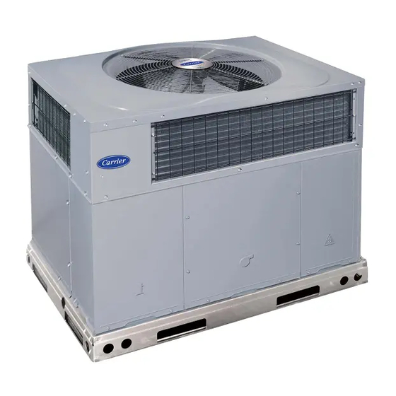
C99001
Fig. 1 - Unit 48DT
Main Burners
...................................
28
Inducer
Pressure Switch
...........................
28
Outdoor
Coil, Indoor ('oil, and Condensate
Drain Pan ....
28
....................................
29
......................
29
Refrigerant
Circuit
................................
29
Indoor Airflow
..................................
29
Metering
Devices-TXV
& AccuRater
Piston
..........
29
................................
29
Loss-of-Charge
Switch
...........................
29
High-Pressure
Switches
...........................
29
Copeland
Scroll Compressor
(Puron (5:Refrigerant)
.......
29
...............................
30
...................................
30
Oil ................................
30
...
30
.........................
30
..............
30
..........................
30-32
FINAL
CHECKS
..................................
32
CARE AND MAINTENANCE
.......................
32
START-UP
CHECKLIST
...........................
36
SAFETY
CONSIDERATIONS
Installation
and servicing
of this equipment
can be hazardous
due to
mechanical
and electrical
components.
Only trained
and qualified
personnel
should install, repair, or service this equipment.
Untrained
personnel
can perform
basic maintenance
functions
such
as cleaning
and replacing
air filters.
All other operations
must be
performed
by trained
service
personnel.
When
working
on this
equipment,
observe
precautions
in the literature,
on tags, and on
labels
attached
to or shipped
with
the
unit
and
other
safety
precautions
that may apply.
Advertisement
Table of Contents


Need help?
Do you have a question about the Infinity 48DT Series and is the answer not in the manual?
Questions and answers