Advertisement
ERVCCSVA1100 ERVCCSHA1100
HRVCCSVA1100 HRVCCSHA1100
ENERGY/HEAT RECOVERY VENTILATOR
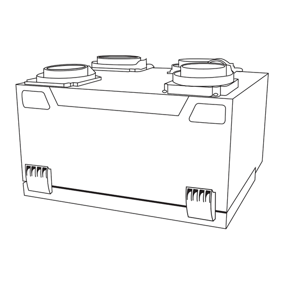
Fig. 1 - - ERV/HRV Unit (Top Port)
Fig. 2 - - ERV/HRV Unit (Side Port)
NOTE: Read the entire instruction manual before starting the
installation.
SAFETY CONSIDERATIONS
Installation and servicing of this equipment can be hazardous due to
mechanical and electrical components. Only trained and qualified
personnel should install, repair, or service this equipment.
Untrained personnel can perform basic maintenance functions such
as cleaning and replacing air filters. All other operations must be
performed by trained service personnel. When working on this
equipment, observe precautions in the literature, on tags, and on
labels attached to or shipped with the unit and other safety
precautions that may apply.
Follow all safety codes. Installation must be in compliance with
local and national building codes. Wear safety glasses, protective
Installation, Start- -up,
and Operating Instructions
A05229
A05330
clothing, and work gloves. Have fire extinguisher available. Read
these instructions thoroughly and follow all warnings or cautions
included in literature and attached to the unit.
Recognize safety information. This is the safety- -alert symbol
When you see this symbol on the unit and in instructions or manuals,
be alert to the potential for personal injury.
Understand these signal words; DANGER, WARNING, and
CAUTION. These words are used with the safety- -alert symbol.
DANGER identifies the most serious hazards which will result in
severe personal injury or death. WARNING signifies hazards which
could result in personal injury or death. CAUTION is used to
identify unsafe practices which may result in minor personal injury
or product and property damage. NOTE is used to highlight
suggestions which will result in enhanced installation, reliability, or
operation.
INTRODUCTION
The Energy/Heat Recovery Ventilator (ERV/HRV) is used to
exchange indoor stale air with outside fresh air. The unit is equipped
with a special energy/heat recovery core which transfers both
sensible and/or latent heat between the fresh incoming air and stale
exhaust air. The cross- -flow design core allows entering and leaving
air streams to transfer heat and/or latent energy without mixing (See
Fig. 14).
The model operates at 2 airflows, 50 CFM in low speed and 100
CFM in high speed. This unit comes in two configurations, vertical
or horizontal. Special attention should be given to duct application,
balancing the ERV/HRV, and locating unit for easy access and
routine maintenance.
INSTALLATION CONSIDERATIONS
Step 1.—Inspect Equipment
Move carton to final installation location. Remove ERV/HRV from
carton taking care not to damage unit. Remove all packaging and
inspect unit for damage. Remove parts bag from inside unit. File
claim with shipping company if shipment is damaged or
incomplete. Check to make sure ERV/HRV unit matches Fig. 1 or
Fig. 2.
Step 2.—Select Location
The ERV/HRV should be located in a conditioned space and in
close proximity to a fused power source. It should be easily
accessible for routine maintenance.
If ERV/HRV is installed independent of a forced- -air system, unit
should be located near the center of the air distribution system. If
ERV/HRV is installed in conjunction with a forced- -air system, unit
should be located next to (or close to) the indoor equipment.
1
!
!
Advertisement
Table of Contents

Related Manuals for Carrier ERVCCSVA1100


Summary of Contents for Carrier ERVCCSVA1100
- Page 1 ERVCCSVA1100 ERVCCSHA1100 HRVCCSVA1100 HRVCCSHA1100 ENERGY/HEAT RECOVERY VENTILATOR Installation, Start- -up, and Operating Instructions clothing, and work gloves. Have fire extinguisher available. Read these instructions thoroughly and follow all warnings or cautions included in literature and attached to the unit. Recognize safety information. This is the safety- -alert symbol When you see this symbol on the unit and in instructions or manuals, be alert to the potential for personal injury.
- Page 2 running both fresh- -air and return- -air registers (or stale- -air pickup ERV ports on side (bottom view) registers) throughout the home. Fresh- -air registers are normally located in bedrooms, dining room, living room, and basement. It is recommended that registers be placed 6 to 12 in.
- Page 3 Step 4.— Connect Ducts to ERV/HRV Step 5.—Locate and Install Exterior Hoods IMPORTANT: To prevent condensation problems, insulated CAUTION flexible ducts are required on both fresh- -air inlet and exhaust- -air outlet ducts connecting between ERV/HRV and exterior wall. PROPERTY DAMAGE HAZARD Fresh- -air intake and stale- -air exhaust must be separated by at least Failure to follow this caution may result in minor 6 ft.
-
Page 4: Exhaust Hood
NOTE: A + B = Not less than 10 feet 3 Ft. MIN FURNACE INSULATED DUCT CONNECTING FRESH AIR & EXHAUST TO OUTSIDE NOTE: Supply & exhaust ducts have internal balancing dampers that must be adjusted. REAR INLET HOOD 6′ EXHAUST HOOD 18″... -
Page 5: Wall Control
WALL CONTROL This control helps avoid condensation problems in upper northern regions where indoor humidity is a problem during the winter Step 1.—Location season. The ERV/HRV wall control is unique to this unit. The ERV/HRV NOTE:This control is not to be confused with a dehumidistat used will not operate without it. -
Page 6: Operation
WALL CONTROL MODE CONTROL CONNECTOR AIR EXCHANGE MAINTENANCE ´ ECHANGE D´AIR BLACK % HUM. RELATIVE HUM. EXT. TEMP. EXT. 10 C/50 F 0 C/32 F GREEN –10 C/14 F –20 C/–4 F YELLOW ´ % D´HUMIDITE RELATIVE HUMIDITY W ARNING A VER TI SS EMENT Risk of electric shock. -
Page 7: Ventilation Evaluation
2. 60 Minute Adjustable Timer A 60 minute adjustable timer can also be used to override wall control and put HRV into high- -speed operation for a select amount of time. Connect timer in parallel with push button timers, or to ERV/HRV terminals OC and OL (See Fig. - Page 8 ELECTRONIC CONTROL THE WIRES FROM THE SWITCH BOARD YELLOW – INDICATOR, (J3- -3) BLACK – COMMON, (J3- -4) RED – SWITCH, (J3- -5) BLACK YELLOW (OPTIONAL) (OPTIONAL) 60 MINUTE TIMER PUSH BUTTON SWITCHES (5 SWITCHES MAXIMUM) (OC) BLACK – (J3- 4) COMMON TERMINAL STRIP...
- Page 9 CONTROL BOARD OPERATION CARE AND MAINTENANCE 1. Defrost 1. Door The ERV/HRV continually monitors the outside air temperature. If ERV/HRV door can be removed by unlatching brief case style the outside air is at or below 23°F(- -5°C), the ERV/HRV will initiate latches, then slide door to the right and remove it from hinges.
-
Page 10: Troubleshooting
WASH- WASH- WASHROOM ROOM ROOM BEDROOM KITCHEN MASTER LIVING ROOM BEDROOM BEDROOM DINING ROOM 1220 sq ft (113 sq m) 1220 sq ft (113 sq m) A05359 Fig. 15 - - Floor Plan Example TROUBLESHOOTING CAUTION NOTE: Reference Table 3 Troubleshooting Chart UNIT COMPONENT DAMAGE HAZARD This can be a quick guide in resolving unit problems. -
Page 11: Control Module
Table 4—Defrost Cycle Outside Temperature HRV Defrost Cycles Operation time (min.) Defrosting (min.) Celcius (°C) Fahrenheit (°F) between each defrost cycle --- 5 to --- 27 23 to --- 17 --- 27 and less --- 17 and less Outside Temperature ERV Defrost Cycles Operation time (min.) Defrosting (min.) - Page 12 Table 6—Temperature/Ohm Relationship Temp. (deg. C) Rst. (k Ohms) Temp. (deg. C) Rst. (k Ohms) 329.5 --- 50 4.911 --- 49 310.9 4.749 --- 48 293.5 4.593 --- 47 277.2 4.443 --- 46 262.0 4.299 --- 45 247.7 4.160 --- 44 234.3 4.026 221.7...
- Page 14 Catalog No: ERVHRV--- 1SI Printed in U.S.A. edition date: 11/05 Copyright 2005 Carrier Corp. S 7310 W. Morris St. S Indianapolis, IN 46231 Manufacturer reserves the right to change, at any time, specifications and designs without notice and without obligations. Replaces: New...
Need help?
Do you have a question about the ERVCCSVA1100 and is the answer not in the manual?
Questions and answers