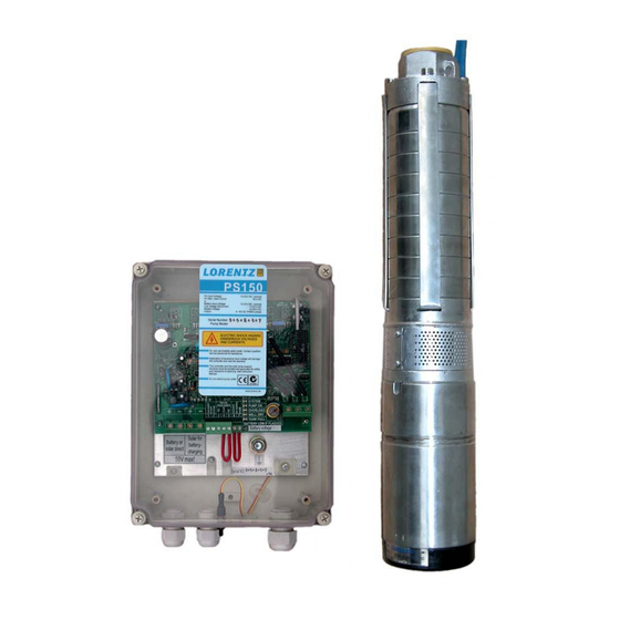
Lorentz PS150 Centric Series Instructions For Installation Operation Service

Lorentz PS150 Centric Series Instructions For Installation Operation Service

Hide thumbs Also See for PS150 Centric Series:

Advertisement

PS150 Centric
Copyright © 2004, 2005 by BERNT LORENTZ KG, all rights reserved.
INSTRUCTIONS FOR
INSTALLATION
OPERATION
SERVICE

Advertisement

Table of Contents
loading
Need help?

Need help?

Do you have a question about the PS150 Centric Series and is the answer not in the manual?

Questions and answers

Subscribe to Our Youtube Channel

Summary of Contents for Lorentz PS150 Centric Series

  • Page 1 PS150 Centric INSTRUCTIONS FOR INSTALLATION OPERATION SERVICE Copyright © 2004, 2005 by BERNT LORENTZ KG, all rights reserved.
  • Page 2: Table Of Contents

    CONTENTS 1 INTRODUCTION 1 INTRODUCTION ............2 Thank you for purchasing a LORENTZ PUMP. We set a new standard for quality and economy in solar pumping. It incorporates the best solar pump technolo- 2 WARNINGS ..............3 gies that were very expensive until its introduction in 2002.
  • Page 3: Warnings

    2 WARNINGS PS150 pumps are different from other pumps. It is a submersible pump. Before beginning installation procedures, these installation and operating instructions should be Failure to follow studied carefully. these instruc- The installation and operation should also be in tions will void accordance with local regulations and accepted the warranty.
  • Page 4: System Report Form

    4 SYSTEM REPORT FORM Before you start, indicate your systems datas. System Voltage Date of Purchase Purchased from Quantity of Batteries Battery Type Quantity of Solar Modules (panels) Solar Module Type Pump Model Pump Serial # Controller Model Controller Serial # Installer: Record the following Installation Date Installed by...
  • Page 5: Installation Controller Ps150

    5 INSTALLATION CONTROLLER PS150 5.1 General Information 5.2 Technical Data > Controlling and monitoring of the motor Input voltage battery: 12 V - 24 V DC > Integrated MPP-tracking and LVD battery protection PV max. open circuit: 50 V DC >...
  • Page 6: Electrical Installation-Terminals

    5.4 Electrical Installation-Terminals Power IN For PV-direct systems, a two-pole discon- to each terminal. If dry run protection is not needed, nect switch may be installed between the solar array short cut these two terminals. and the controller. Switch it off to prevent shock and arc No.
  • Page 7: Wiring Order For Correct Rotation

    5.6 Wiring Order for Correct Rotation The power wires on the pump are black with the direction is wrong, exchange ANY TWO of white lettering to indicate L1, L2 and L3. the power wires at the controller. In any case, WRITE DOWN the colors that you splice to when you are finished connecting the pump L1/ L2 / L3 so you can match them with the...
  • Page 8: System Wiring

    7.1 System Wiring for 12 V Battery Installation Controller PS150 combined charge and pump controller 12 V system: Voltage from panels Battery or Solar for Solar Direct Battery Charging will read 22-25 V when discon- SYSTEM remote 50 V max. float switch nected (open circuit).
  • Page 9: System Wiring For 12-24 V Solar Direct Operation

    7.3 System Wiring for 12-24 V Solar Direct Operation Controller PS150 combined charge and pump controller 12-24 V Solar direct system: Solar for Battery or Solar Direct Battery Charging Voltage from panels will read 22- SYSTEM remote 50 V max. float switch PUMP ON 44 V when disconnected (open...
  • Page 10: Troubleshooting

    8 TROUBLESHOOTING Please read this section before calling for help. If you call for help, please refer to the model and serial numbers. If The Pump Doesn’t Run PUMP OVERLOAD (PUMP ON light shows red instead of green) The system has shut Most problems are caused by wrong connec- off due to an overload.

This manual is also suitable for:

Ps150-cC-sj5-8

Table of Contents