
Related Manuals for Lorentz PS150 BOOST


Summary of Contents for Lorentz PS150 BOOST
- Page 1 PS150 BOOST INSTRUCTIONS FOR INSTALLATION OPERATION SERVICE Copyright © 2004, 2005, 2006, 2007 by BERNT LORENTZ GmbH&CoKG, all rights reserved.
-
Page 2: Table Of Contents
This results in an exceptional high 7 MOUNTING YOUR PUMP ..........8 efficiency with low temperature dissipation. PS150 BOOST can either be used in a battery system 8 INSTALLATION IN DRILLED WELL CASINGS ..... 9 with voltages of 12, 24V or alternatively it can be operated as a solar direct system using the same 9 ELECTRICAL WIRING .......... -
Page 3: Warnings
2 WARNINGS PS150 BOOST IS A DC VANE TYPE PUMP. It is different from other pumps. This is not a submersible pump. Before beginning installation procedures, these Please note: The Failure to follow installation and operating instructions should be pump must only these instruc- studied carefully. -
Page 4: System Report Form
4 SYSTEM REPORT FORM Before you start, indicate your systems datas. System Voltage Date of Purchase Purchased from Quantity of Batteries Battery Type Quantity of Solar Modules (panels) Solar Module Type Pump Model Pump Serial # Controller Model Controller Serial # Installer: Record the following Installation Date Installed by... -
Page 5: Installation Controller Ps150
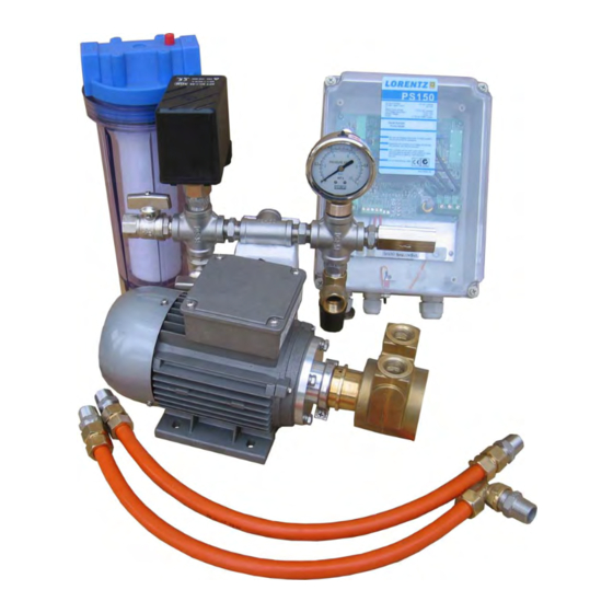
5 INSTALLATION CONTROLLER PS150 5.1 General Information 5.2 Technical Data > Controlling and monitoring of the motor Input voltage battery: 12 V - 24 V DC > Integrated MPP-tracking and LVD battery protection PV max. open circuit: 50 V DC >... -
Page 6: Electrical Installation-Terminals
5.4 Electrical Installation-Terminals Power IN For PV-direct systems, a two-pole discon- to each terminal. If dry run protection is not needed, nect switch may be installed between the solar array short cut these two terminals. and the controller. Switch it off to prevent shock and arc No. -
Page 7: Basic Operating Constraints
5.6 Basic Operating Constraints 1. PUMP IS NOT SUBMERSIBLE resistance to flow, and cost more. Use them only if you have, taste and odor problems. Your pump must NOT be submerged in water, or rained or dripped on. A filter cartridge may look clean and still be clogged, due to fine silt embedded in the fibers. -
Page 8: Mounting Your Pump
Plumbing System Design Continued WEAR. A slight buzzing noise is acceptable, if it cannot water source. A removable plug or a valve must be be avoided. installed at the highest point is in the suction plumbing. Prime the pump and intake line by pouring water into DO NOT USE THIN WALL HOSE or soft tubing on the the opening until it is completely full. -
Page 9: Installation In Drilled Well Casings
8 INSTALLATION IN DRILLED WELL CASINGS INSIDE A 6 INCH WELL CASING, SPECIAL ELBOWS POLYETHYLENE PIPE comes in rolls, and is inexpen- ADAPTERS are required. The elbows fit 1/2" sive and quite freeze tolerant. Use with plastic adapters polyethylene (black flex) pipe. MEASURE CAREFULLY and secure with ALL STAINLESS hose clamps (obtain to determine the length of pipe you need. -
Page 10: System Wiring For 12 V Battery Installation
1 Batteriy, 12 V 1 Solar Panel, 12 V PS150 Boost 9.4 System Wiring for 24 V Battery Installation Controller PS150 combined charge and pump controller “Series” Wiring is shown, for... -
Page 11: System Wiring For 12-24 V Solar Direct Operation
12.0 / #6 14.0 / #6 9.6 Power Control for Solar Direct Operation PS150 BOOST requires nearly constant current, regardless of the voltage/speed. When low light conditions are present, the PV array cannot supply full current. The voltage will drop to nearly zero, and the pump will “stall”... -
Page 12: Water Level And Flow Control
Pressure should NOT be set beyond 4.5 bar/ Fee Pipe Pressure Tank from Suction Foot Valve Well Pump Pipe Priming Pressure Plug PS150 BOOST Pump Switch Installation: From cistern or storage tank, Check where pump must be To House Valve Plumbing higher than source. Pressure... -
Page 13: Pressure Switch Wiring
1300 dealer, or the factory. The best way to determine when a SERIES “PS150 BOOST” has an angled extension with cartridge is becoming clogged is to listen for an a large brass nut on the end. Remove the nut to inspect increasingly loud buzzing noise (cavitation). -
Page 14: Troubleshooting
13 TROUBLESHOOTING PUMP WILL NOT FIT INTO YOUR 5" OR 6" DRILLED FILTER CLOGS FREQUENTLY: (1) INTAKE TOO CLOSE to WELL CASING: Special elbow fittings are required. bottom of well, stream, tank etc. Raise it as high as Contact dealer or factory. feasible to reduce intake of dirt. -
Page 15: Warranty
PUMP RUNS TOO SLOW OR STALLS IN LOW LIGHT Pump Rotor / Stator / Vanes of PS150 BOOST Motor / (Array Direct, Non Battery System): (1) Solar array or Pump are considered to be normally wearing parts, wire is undersized. - Page 16 Bernt Lorentz GmbH & Co. KG Heidekoppel 16 D-24558 Henstedt-Ulzburg Germany Tel. ++49.4193.7548-0 ++49.4193.7548-29 www.lorentz.de info@lorentz.de Copyright © 2004, 2005 by BERNT LORENTZ KG, all rights reserved.
Need help?
Do you have a question about the PS150 BOOST and is the answer not in the manual?
Questions and answers