Lorentz PS1200 Instructions For Installation Operattion Service
Solar water
pump systems
Hide thumbs
Also See for PS1200:
- Installation operation & maintenance (51 pages) ,
- Instructions for installation operation service (68 pages) ,
- Solar pumping planning manual (25 pages)
Advertisement
Table of Contents
- 1 Electrical Installation
- 2 Disconnect Switch
- 3 Wiring Order for Correct Rotation
- 4 Battery-Based Systems
- 5 Operating the Pump
- 6 Power On/Off
- 7 Pump Overload
- 8 Troubleshooting
- 9 System Wiring Diagram for Solar-Direct (Non-Battery) System
- 10 Pump Motor
- 11 System Report Form
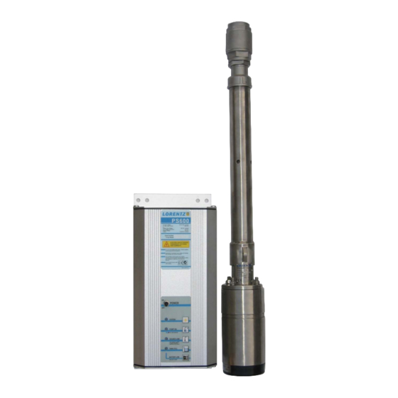
- 12 System and Components
- 13 Installation Report
- Download this manual
See also:
Installation Operation & Maintenance
Advertisement
Table of Contents

Subscribe to Our Youtube Channel
Related Manuals for Lorentz PS1200


Summary of Contents for Lorentz PS1200
- Page 1 PS200 PS600 PS1200 SOLAR WATER PUMP SYSTEMS INSTRUCTIONS FOR INSTALLATION OPERATION SERVICE Bernt Lorentz GmbH & Co. KG Heidekoppel 16 D-24558 Henstedt-Ulzburg Germany Tel. ++49.4193.7548-0 ++49.4193.7548-29 www.lorentz.de info@lorentz.de release 05/04/07...
- Page 2 Undersized wire will cause failure to start. PS200-, above 150V for PS600- and above Do not touch the controller input or pump 200V for PS1200 controllers will destroy the wires together to test for a spark. controller. This may occur if the solar array is Do not run the pump dry.
-
Page 3: Electrical Installation
Do not connect any electrical load to the vertically to keep out rainwater. It is preferable connections to solar array if it is not part of the LORENTZ to mount it ON THE NORTH SIDE of a pole or the controller. -
Page 4: Wiring Order For Correct Rotation
Wiring Order for Correct Rotation The power wires on the pump are black with the direction is wrong, exchange ANY TWO of white lettering to indicate L1, L2 and L3. the power wires at the controller. In any case, WRITE DOWN the colors that you splice to when you are finished connecting the pump L1/ L2 / L3 so you can match them with the to the controller, test it to assure the proper... -
Page 5: Battery-Based Systems
Battery-Based Systems PS-XXX pump systems can be operated Wire Sizing for the DC circuit Wire must be from batteries. sized for no more than 5% voltage drop at 20 amps (starting). Refer to a wire sizing chart specifically for 24V Install a jumper wire between terminals 6 or 48V, or follow these examples: and 7 to set the controller to battery mode. -
Page 6: Operating The Pump
OPERATING THE PUMP This explains the function of the switch and SWITCH the indicator lights on the pump controller. POWER ON/OFF When switched off/on during operation, it resets all system logic. Indicator lights SYSTEM (green) The controller is switched on and the power source is present. -
Page 7: Pump Overload
Operating the Pump continued Starting the pump Be sure there is not a Time delays closed valve or other obstruction in the water 1. After pump stops due to insufficient line. Switch on the array disconnect switch in sunshine – 120 SECONDS the junction box, and toggle the power switch 2. -
Page 8: Troubleshooting
TROUBLE SHOOTING Please read this section before calling for help. If you call for help, please refer to the model and serial numbers. CAUTION DO NOT REMOVE THE CHECK If The Pump Doesn’t Run VALVE from the pump. If you want to look for dirt Most problems are caused by wrong connec- stuck inside the... -
Page 9: System Wiring Diagram For Solar-Direct (Non-Battery) System
It must be within a range of PS200 : 35-90V DC PS600 : 75-135V DC PS1200: 110- 180V DC Float Switch (optional) Float Switch Kit makes contact on rise to stop pump. Connect termins 3 (NO) and 4... -
Page 10: System Report Form
Date of Purchase Purchased from Battery System? if not: Quantity of Solar Modules (panels) Solar Module Brand Module Model # Controller Model PS1200 PS600 PS200 other, i.e.: Controller Serial # Pump End Model # Pump End Serial # Temperature Range... -
Page 11: Installation Report
System Report Form continued Installation Report Installation Date Well Depth m / ft Pump depth m / ft Additional Vertical Lift (up to top of tank) m / ft Static Water Level m / ft Drawdown level m / ft Drop Pipe (vertical from the pump) Size / inch...
Need help?
Do you have a question about the PS1200 and is the answer not in the manual?
Questions and answers